Horizontal-Schrumpfgerät
Horizontal Shrinking Device
HS 1100-P
Copyright © Diebold 2017-04 Ersteller: kh
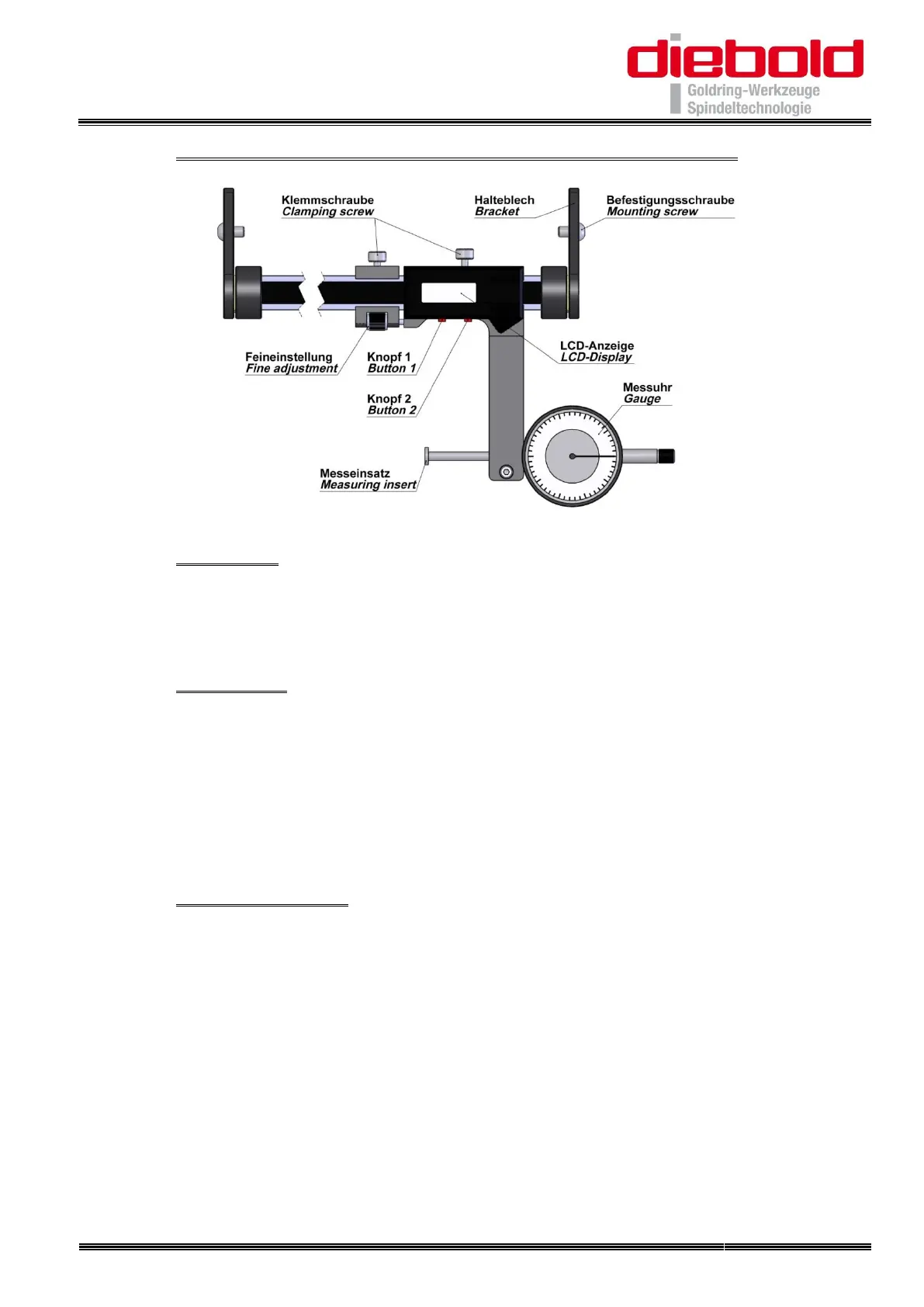
21. Operation of the Length Setting Unit (Optional)
21.1. Assembly
The Length Setting Unit is fixed with 4 screws on the side panel. The device must be
aligned so that the center of the gauge is approximately in the middle when using short
and long cutting tools
21.2. Measuring
After the correct tool holder has been mounted on the shrinking device, the LCD
display reference dimension (leading edge of the tool holder) has to be set to "zero"
first. For this purpose, the gauge sensor contacts the front edge of the tool holder. The
fine adjustment should be adjusted so that the flat side is contacted. Set the dial
indicator to "zero" position and the LCD display with "Button 2" to "zero". Then the
required extension length "Z dimension" can be set. Tighten the clamping screws on
the LCD display and fine adjustment.
21.3. Shrink on length
Insert the cutting tool into the opening of shrink fit chuck. Use the appropriate ferrite
disc inside the coil. Push the coil stop (disc) above the shrink fit chuck. Start shrinking
process with the “Start/Stop” button.
For small cutting tools with a short shank, insert the cutting tool into the receiving bore ,
pull back and lock the gauge. Then insert the cutting tool until the gauge reaches the
"zero" position. By tracking the dial gauge with fine adjustment check whether cutting
tool has not been pushed too far.
For large shafts first heat the shrink chuck then insert the cutter, swivel the dial gauge
and set the cutting tip against the dial plate or slide cutter with dial plate in position.