4
5
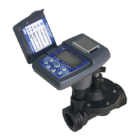
Figure 5a
WATER
FLOW
Figure 5b
Additional control valves must not be installed downstream of the anti-
siphon valve. The valve must not be operated continuously for more
than 12 hours in any 24-hour period. Consult local codes for speci c
details.
1. Flush main line until water runs clear before installation.
2. Shut off main water supply.
3. Install the anti-siphon valve directly to PVC pipe using 3⁄4 in. PVC
male adapters (Figure 5a and 5b) or use 3/4 in. schedule 80 nipple.
The arrow on valve body indicates direction of water ow.
NOTE: Wrap all ttings with Te on tape. Do not use pipe cement on
the valve as this will damage the valve and void the warranty. Make
sure when wrapping ttings with Te on tape that no excess gets into
the internal assembly. Tighten the ttings with a wrench, but do not
over tighten.
4. Turn the main water supply on and pressurize the system.
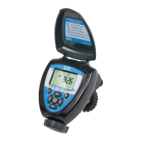
5. To test the 410BT-ASV, press the button on the unit. A click will be
heard, indicating the valve is open. Check that the system is
operating correctly and press the button again to turn it off. A
second click will be heard indicating that the valve closed.
6. The unit is now ready to be programmed.
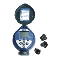
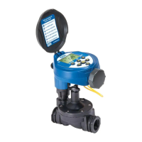
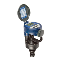
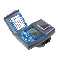
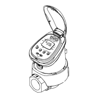
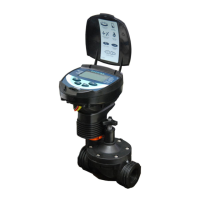
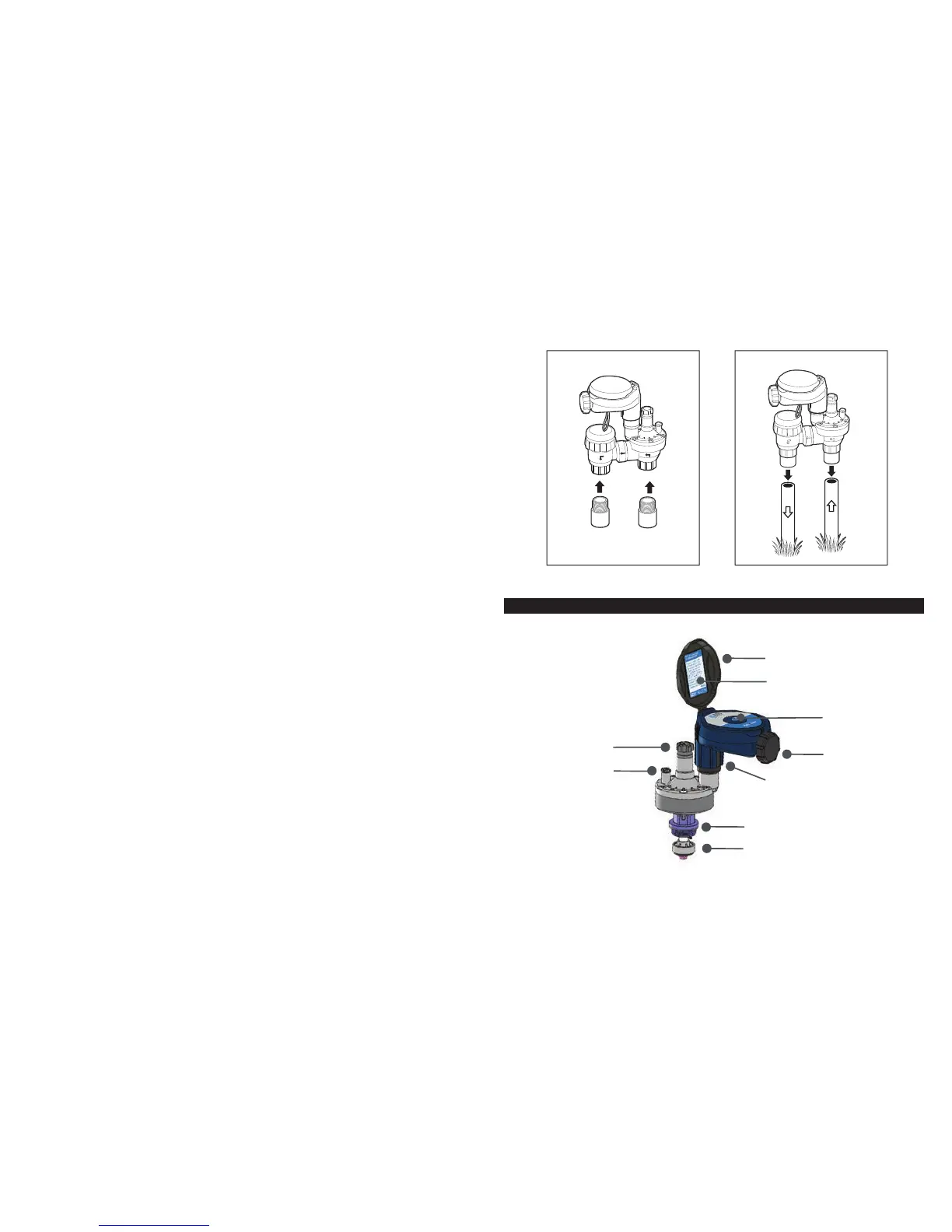
6. MVA COMPONENT IDENTIFICATION
One button
for manual
run and reset
Battery
compartment cap
3/4 in adapter
3/4 in seat washer
Lid
FCC label
Solenoid
Manual fl ow control
External bleed screw
 Loading...