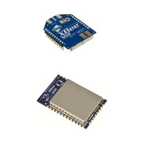
XBee® Wi-Fi RF Modules
© 2013 Digi International, Inc. 100
AT
Command
Name and Description
Parameter
Range
Default
P7** DIO17 Configuration. Select/Read function for the DIO17 line of the RF module.
0 = Disabled
1 = SPI_nSSEL
4 = Digital output,
default low
5 = Digital output,
1
P8** DIO18 Configuration. Select/Read function for the DIO18 line of the RF module.
0 = Disabled
1 = SPI_CLK
4 = Digital output,
default low
5 = Digital output,
1
P9** DIO19 Configuration. Select/Read function for the DIO19 line of the RF module.
0 = Disabled
1 = SPI_nATTN
4 = Digital output,
default low
5 = Digital output,
default high
6 = UART data
present indicator
1
D0 DIO0/AD0 Configuration. Select/Read function for DIO0/AD0.
2 = Analog input
3 = Digital input,
monitored
4 = Digital output,
default low
5 = Digital output,
default high
0
D1 DIO1/AD1 Configuration. Select/Read function for DIO1/AD1
0 - Disabled
1 = SPI_nATTN*
2 = Analog input
3 = Digital input,
monitored
4 = Digital output,
default low
5 = Digital output,
default high
0
D2 DIO2/AD2 Configuration. Select/Read function for DIO2/AD2
1 = SPI _CLK*
2 = Analog input
3 = Digital input,
monitored
4 = Digital output,
default low
5 = Digital output,
0
D3 DIO3/AD3 Configuration. Select/Read function for DIO3/AD3
0 = Disabled
1 = SPI Slave Select*
2 = Analog input
3 = Digital input,
monitored
4 = Digital output,
default low
5 = Digital output,
default high
0
D4 DIO4 Configuration. Select/Read function for DIO4
0 = Disabled
1 = SPI_MOSI*
3 = Digital input,
monitored
4 = Digital output,
default low
5 = Digital output,
0

 Loading...