Description
3.1
3. DESCRIPTION
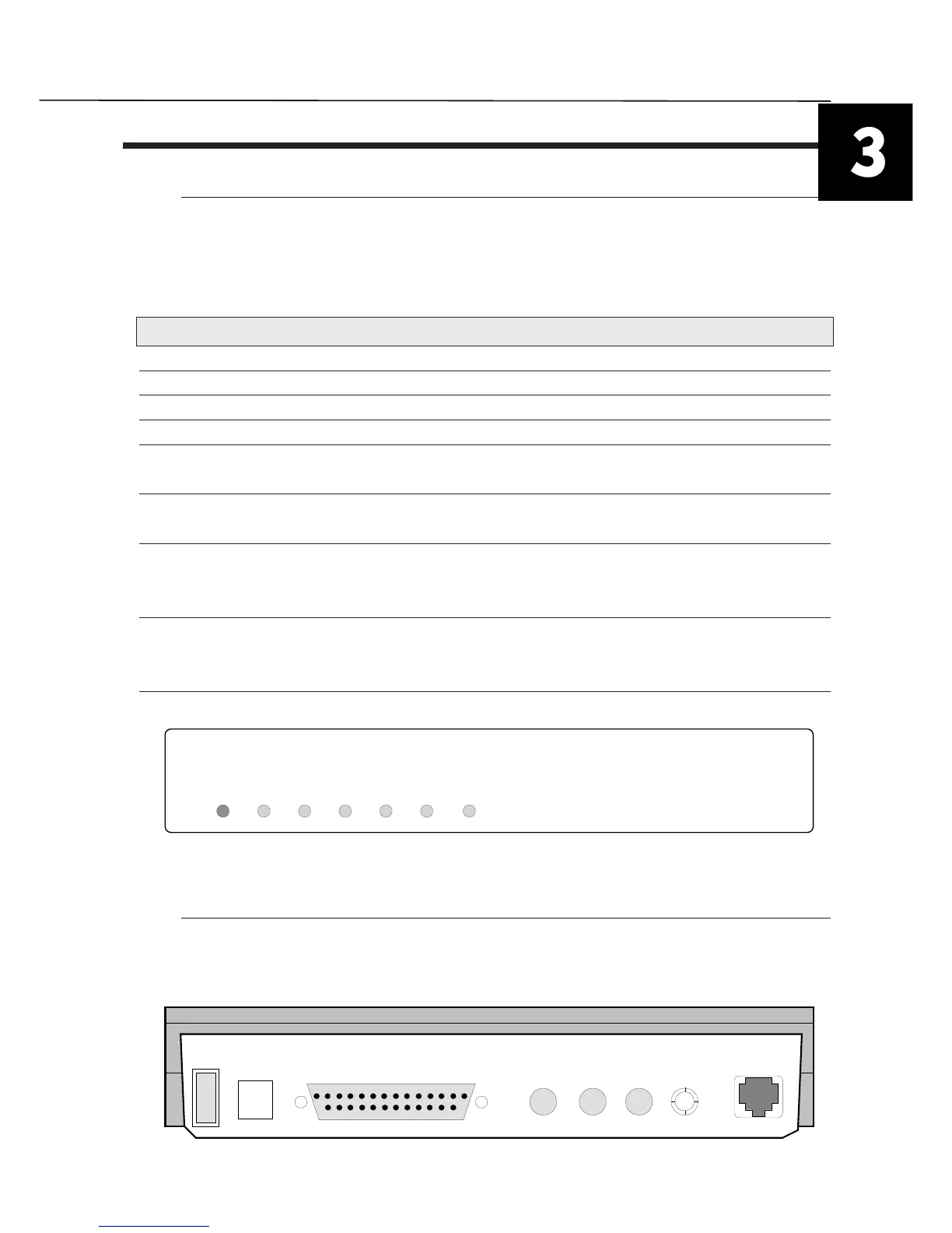
3.1. FRONT PANEL EXTERNAL VERSION
On the front panel are present LED that indicate the most important interface circuit in use
and one push-button for TEST functions. In the following table, is present the complete
description and function of each LED:
NAME COLOR STATUS FUNCTION
PWR green on Tintoretto powered ON
DTR red on Computer ready
TD red on Transmit data
RD red on Received Data
TEST red on Tintoretto on test
flashing Error during the initial Self Test
EC red on Error corrector enable
off Error corrector disable
B1 red on B1 channel in use
off B1 channel inactive
flashing B1 channel busy
B2 red on B2 channel in use
off B2 channel inactive
flashing B2 channel busy
TEST push-button Active the Loop 3 test (Local Loop)
MODEM ISDN ATTIVO
PWR DTR TD RD EC B1 B2
Fig.3.1. Tintoretto front view
3.2. REAR PANEL EXTERNAL VERSION
On the rear panel are present the power switch, the V24 interface connectors and the RJ45
ISDN network connectors.
PWR RS232 JA JB JC JDON LINE
Fig.3.2. Tintoretto Rear Panel