3.2
Description
3.3. HARDWARE SETUP EXTERNAL VERSION
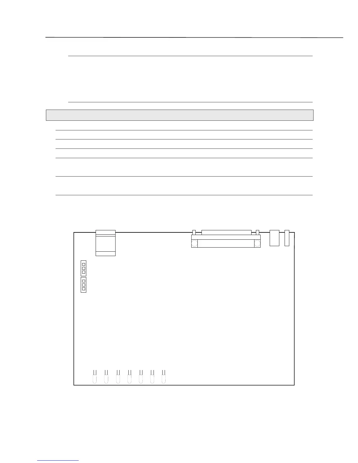
Inside Tintoretto is present a four position dip switch and some jumper berg for the hardware
setup.
3.3.1. JUMPER SETUP
JUMPER POSITION DESCRIPTION DEFAULT
U1 1-2 Transmit Termination 100 ohm
U1 2-3 The transmission channel is in high impedence
l
U2 1-2 Receive Termination 100 ohm
U2 2-3 The receive channel is in high impedence
l
U13 to U19 1-2 The serial interface is V.24 (RS232)
2-3 The serial interface is V.35
U48 to U49 1-2 The serial interface is V.24 (RS232)
2-3 The serial interface is V.35
Normally it is not neccessary modify the default predisposition of the jumpers.
1
1
PWR
RS232
LINE
U1
U2
Fig.3.3. Tintoretto Internal Board