DSE Model 5220 Automatic Mains Failure & Instrumentation System Operators Manual
5220 OPERATING MANUAL ISSUE 5.1 18-Jun-07 AM 5
1 INTRODUCTION
The DSE 5220 automatic mains failure module has been designed to allow the OEM to meet most of the industry’s
complex specifications. It has been primarily designed to monitor the mains (utility) supply, starting the generator
automatically should it fall out of limits. Transfer of the load is automatic upon a mains supply failure. If required the
generator and can be started and stopped manually, and if required, the user can transfer the load to the generator
either manually (via external push-buttons) or automatically. The user also has the facility to view all the system
operating parameters via the LCD display.
The DSE 5220 module monitors the mains (utility) supply indicating the status of the mains on the module’s
integral LCD display. Additionally the module monitors the engine, indicating the operational status and fault
conditions, automatically shutting down the engine and giving a true first up fault condition of an engine failure by a
flashing common alarm LCD indicator. The exact failure mode is indicated by combined “hidden ‘til lit” LEDs and
the LCD display on the front panel.
The powerful microprocessor contained within the module allows for a range of complex features to be
incorporated as standard:
• Graphical Icon based LCD display (excluding the need for translations and languages).
• Voltage, Current and Power monitoring.
• Engine parameter monitoring.
• Fully configurable inputs for use as alarms or a range of different functions.
• Extensive range output functions using built in relay outputs or relay expansion available.
Selective operational sequences, timers and alarm trips can be altered by the customer via a PC using the 5200
series configuration software and P810 interface. Additionally, a subset of this information can be adjusted from the
module’s front panel configuration editor.
The module is housed in a robust plastic case for front panel mounting. Connections to the module are via locking
plug and sockets.
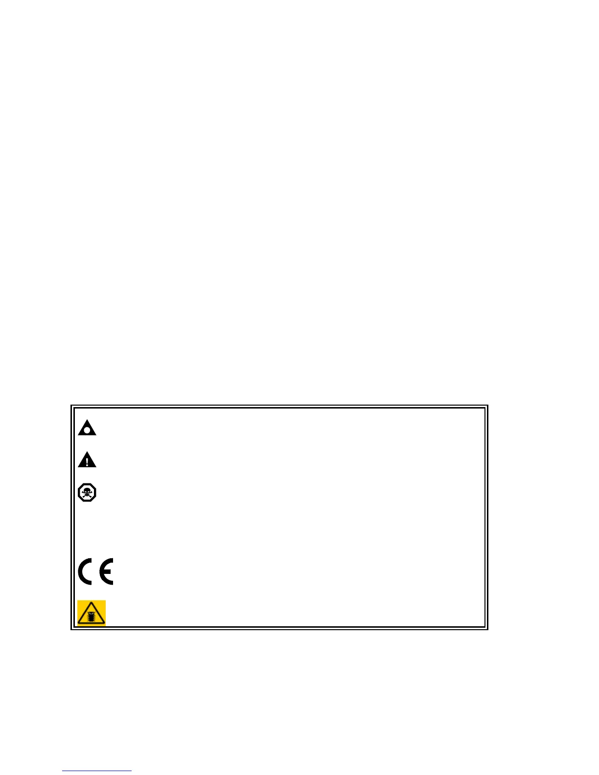
2 CLARIFICATION OF NOTATION USED WITHIN THIS PUBLICATION.
NOTE:
Highlights an essential element of a procedure to ensure
correctness.
CAUTION!
Indicates a procedure or practice which, if not strictly observed,
could result in damage or destruction of equipment.
WARNING!
Indicates a procedure or practice, which could result in injury to
personnel or loss of life if not followed correctly.
©
Deep Sea Electronics Plc owns the copyright to this manual, which
cannot be copied, reproduced or disclosed to a third party without
prior written permission.
Compliant with BS EN 60950 Low Voltage Directive
Compliant with BS EN 50081-2 EMC Directive
Compliant with BS EN 50082-2 EMC Directive
 Loading...