DSE Model 5220 Automatic Mains Failure & Instrumentation System Operators Manual
24 057-012 5220 OPERATING MANUAL ISSUE 5.1 18/06/2007 AM
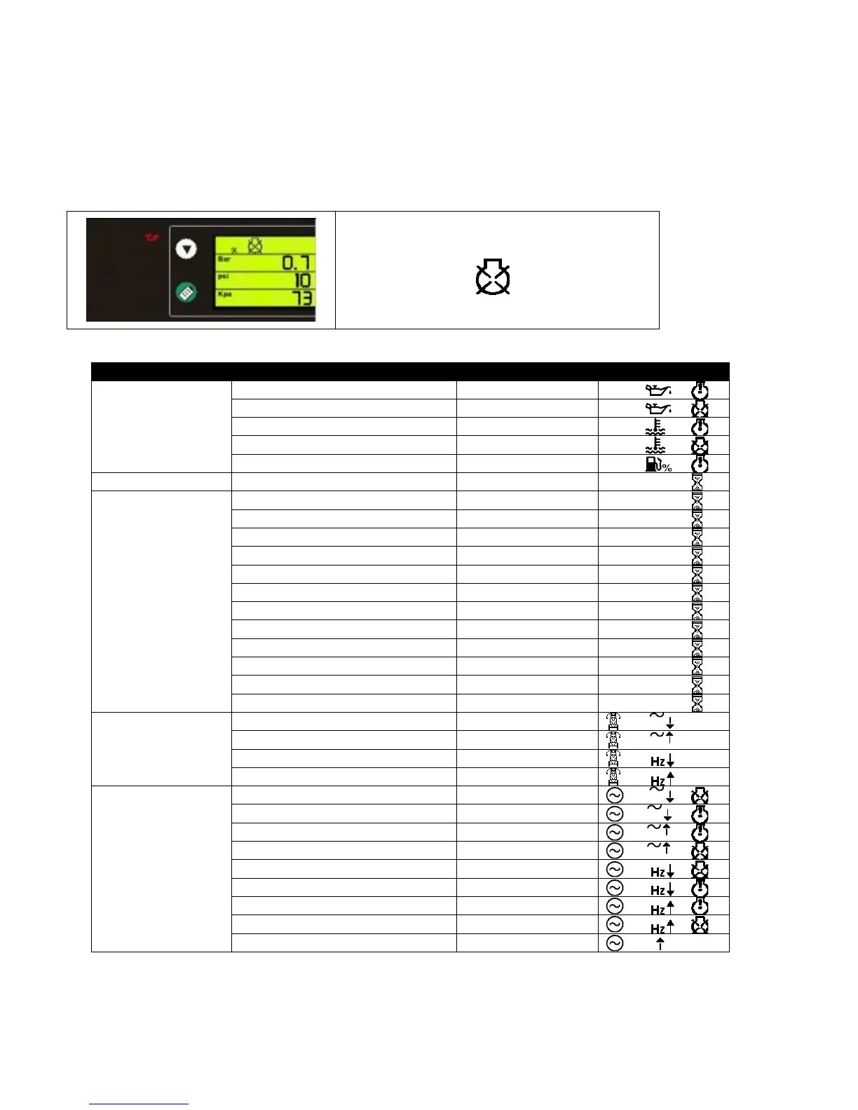
7.1.2 EDITING AN ANALOGUE VALUE
Press the 9 button to enter edit mode. This is indicated by the flashing parameter. In this example, entering edit
mode will cause the 1.2 value to flash.
When in edit mode, pressing the
+ or – buttons will adjust the parameter to the desired value. Press the 9
button to ‘save’ the value. The value will stop flashing to confirm that it has been saved.
To select another value to edit, press the
+ button :
The next parameter being displayed in this example
is the Low Oil Pressure shutdown, being indicated
by the illuminated oil can.
The shutdown symbol
is indicating that it is
the shutdown (trip) parameter that is being
displayed.
Continuing to press the + or – buttons will cycle through the adjustable parameters in the following order :
Config’ Section Parameter Type Icons displayed
Analogue senders
Low Pressure Pre Alarm
Low Pressure Trip
High Temperature Pre Alarm
High Temperature Trip
Fuel Level % Pre Alarm
Calendar Date/time Date/time
Timers
Mains transient delay Timer (secs)
1
Start delay Timer (secs)
2
Preheat Timer (secs)
3
Crank attempt Timer (secs)
4
Crank rest Timer (secs)
5
Safety delay Timer (secs)
6
Overspeed overshoot Timer (secs)
7
Warming up Timer (secs)
8
Transfer delay Timer (secs)
9
Return delay Timer (secs)
10
Cooling run Timer (secs)
11
E.T.S.(Energise to stop) solenoid hold Timer (secs)
12
Mains (utility) supply
Mains Low Voltage Trip
Generator Under Frequency Trip
Generator Under Frequency Pre Alarm
Generator Over Frequency Pre Alarm
Generator Over Frequency Trip
Delayed Overcurrent % Trip
A
 Loading...