SYSTEM 3000 to 3505 CONVERSION MANUAL
DIGITIZE, INC. 700254-0001 REV B 02/04
Specifications Subject to Change Without Notice
2-3
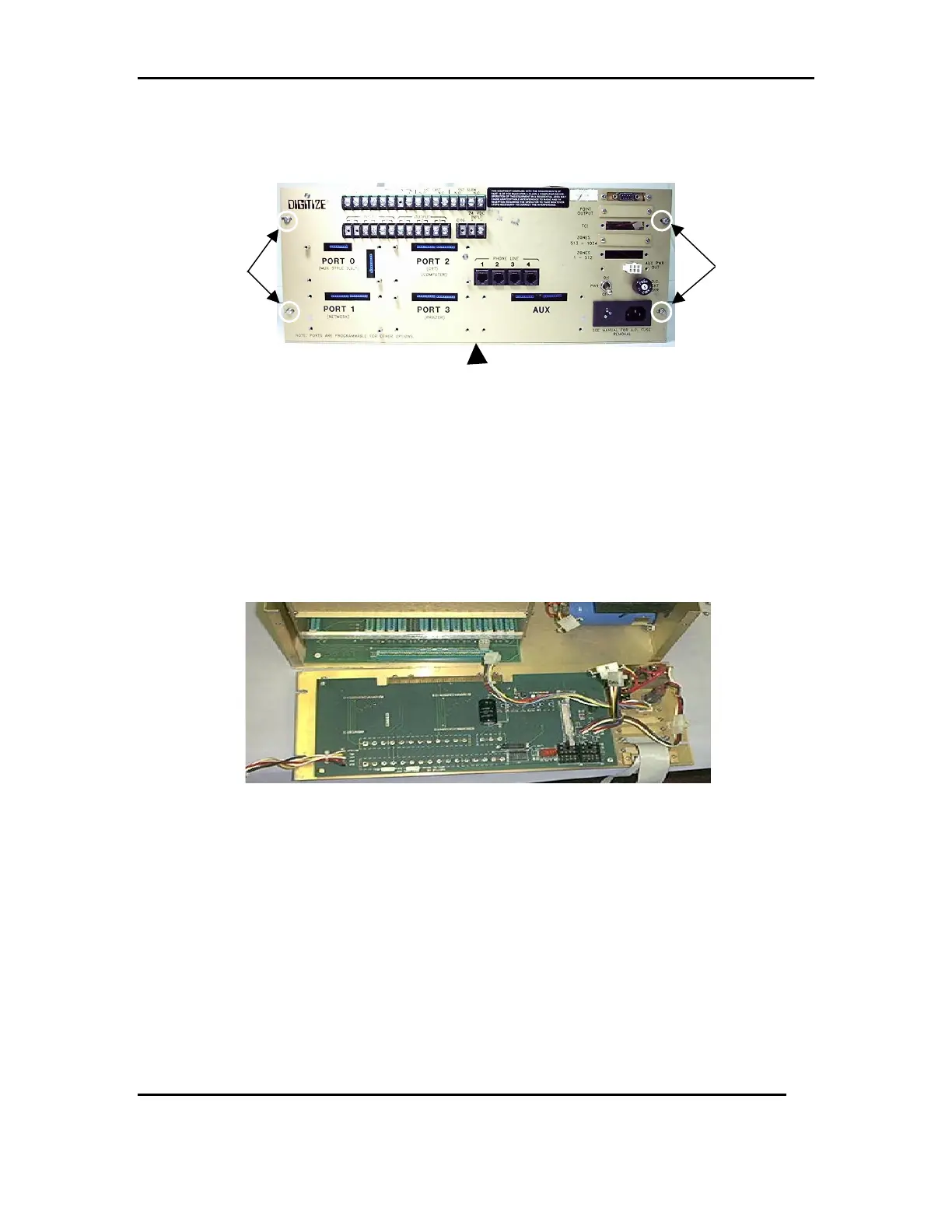
2.6 Remove the slotted screws holding the rear panel in place. To remove the rear panel,
lift up to disengage it from the motherboard. Refer to FIG 7a & 7b
2.6.1 Remove any additional hardware if installed from the rear panel and save for
installation on the new rear panel.
1. SST Relays and spring clips, K0 and K1.
2. Any 26 pin ribbon cable and hardware, ZONES 1-512, ZONES 513-1024, TCI,
or POINT OUTPUT.
3. If so equipped the AUX PWR OUT cable will not be needed in the 3505.
FIG 7b
2.7 Disconnect the cable between the 9000UF 50V RADIAL CAP (P/N: 900111-0019)
and the Cable CF2 W/ Transformer assembly (P/N: 450294-0004). Refer to FIG 8a
2.7.1 Remove the four screws holding the transformer in place. Refer to FIG 8b
LIFT UP
FIG 7a
REMOVE
REMOVE