8 www.dimplex.com
Installation
feet on the bottom of the unit.
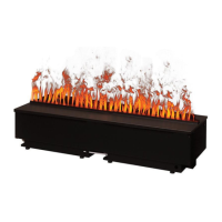
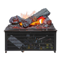
Logset - 40 ⅜ in. (1025 mm)
wide, 14 ¼ in. (360 mm) deep
and the height can be adjusted
from 9 in. (229 mm) to 9 ½ in.
(241 mm) by turning the feet on
the bottom of the unit
!
NOTE: It is recommended
that during drywall installation and
nishing the media tray be installed
with the provided bag to prevent
dust and debris from entering the
unit.
!
NOTE: For optimal perform-
ance, a clearance of 18 in. (457
mm) between the installation sur-
face and any surface above should
be maintained. A minimum clear-
ance of 12 in. (305 mm) must be
maintained.
2. In the back right corner of the
unit, locate and remove the
electrical cover plate, by remov-
ing the two securing screws.
3. Install a ⅜ in. (10 mm) or ½ in.
(13 mm) cable connector, not
included, suitable for mounting
in a ⅞ in. (22 mm) hole, to the
cable plate and feed the supply
cable through the connector.
The cable plate can be removed
by removing the two securing
screws on either side, to allow
for easier access.
CAUTION: Use two conductor,
non-metallic sheath cable with
ground wire (3 wires total) for the
incoming power supply on replace
inserts. Use appropriate wire to
meet local and national electrical
codes for rated power.
!
NOTE: When installing multiple
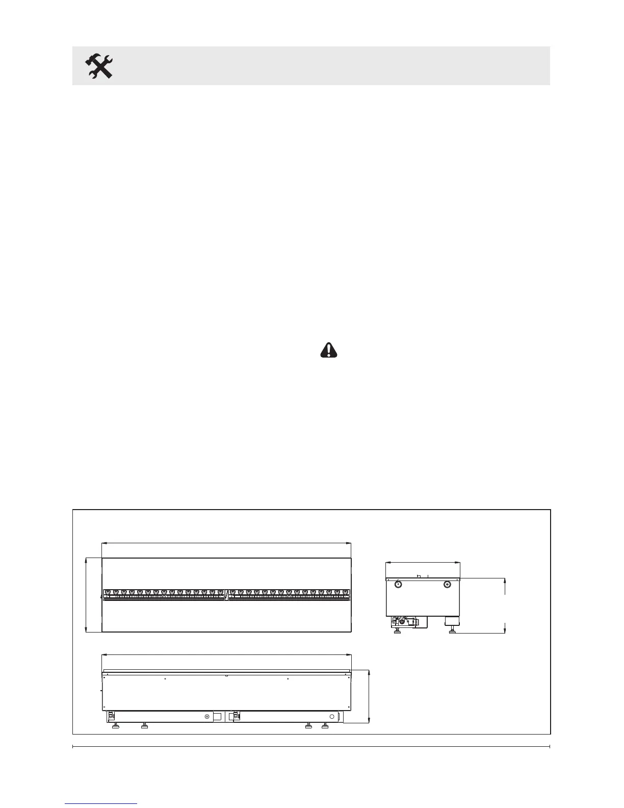
8.50 in. (216 mm)
40.08 in. (1018 mm)
Logset: 13.94 in. (353 mm)
Adjustable from
9.0 in. (224 mm)
to 9.5 in. (241 mm)
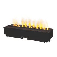
11.94 in. (303 mm)
40.08 in. (1018 mm)
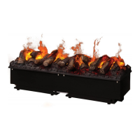
Media Plate: 11.94 in. (303 mm)
!
NOTE: When prepar-
ing the opening for the unit
¼ in. (6.4 mm) of clearance
should be maintained from
each surface to ensure easy
installation.
Product Dimensions