18 www.dimplex.com
Test Mode
Test Mode has been integrated into this product to improve end-of-line testing during production and can be used
to isolate components for individual function testing. Test mode should be conducted by trained personnel only.
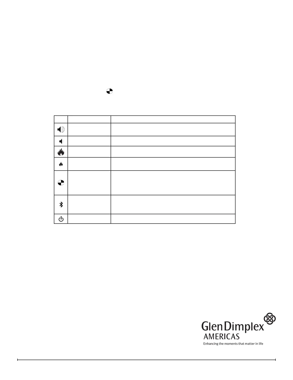
The icons on the On Board Control buttons (Figure 1) do not match the commands they are associated with,
when in test mode.
1. Ensure unit is connected to power and water is supplied.
2. Remove logs or top plate and set aside.
3. Press power switch on (Figure 1A). Presence of power will be indicated by one beep
4. Press the troubleshooting button (Figure 1D) on the side that the testing is required, unit will beep.
5. Press the following buttons to test functionality of listed components - press once will turn On and press
again to turn o
Component Test Expected Functionality
LED Assembly /
LED Driver
Lights turn on
Sound
Crackling sound turns on
Fan
Fan turns on
Transducer
Transducer will turns on and bubbling will be seen
coming out of the transducer
Solenoids
Solenoids will turn On (the main solenoid coming in and
the solenoid on the side being tested). The sound
of the solenoids can be heard (a slight thump), and
possibly the sound of water owing.
Heater Relay
Relays will be activated to turn the heating element on,
a quiet clicking noise can be heard. The element will
get warm.
Log Set
LEDs in log set will turn on (if present)
6. After 15 seconds of inactivity the unit will beep and then return to regular Standby mode, or the On/O
button can be switched to O to end the test mode.
REV PCN DATE
00 - 21-12-15
01 - 31-07-19
02 - 07-10-19
03 - 08-07-20
1-888-346-7539 | www.dimplex.com
In keeping with our policy of continuous product improvement,
we reserve the right to make changes without notice.
© 2020 Glen Dimplex Americas