6 www.dimplex.com
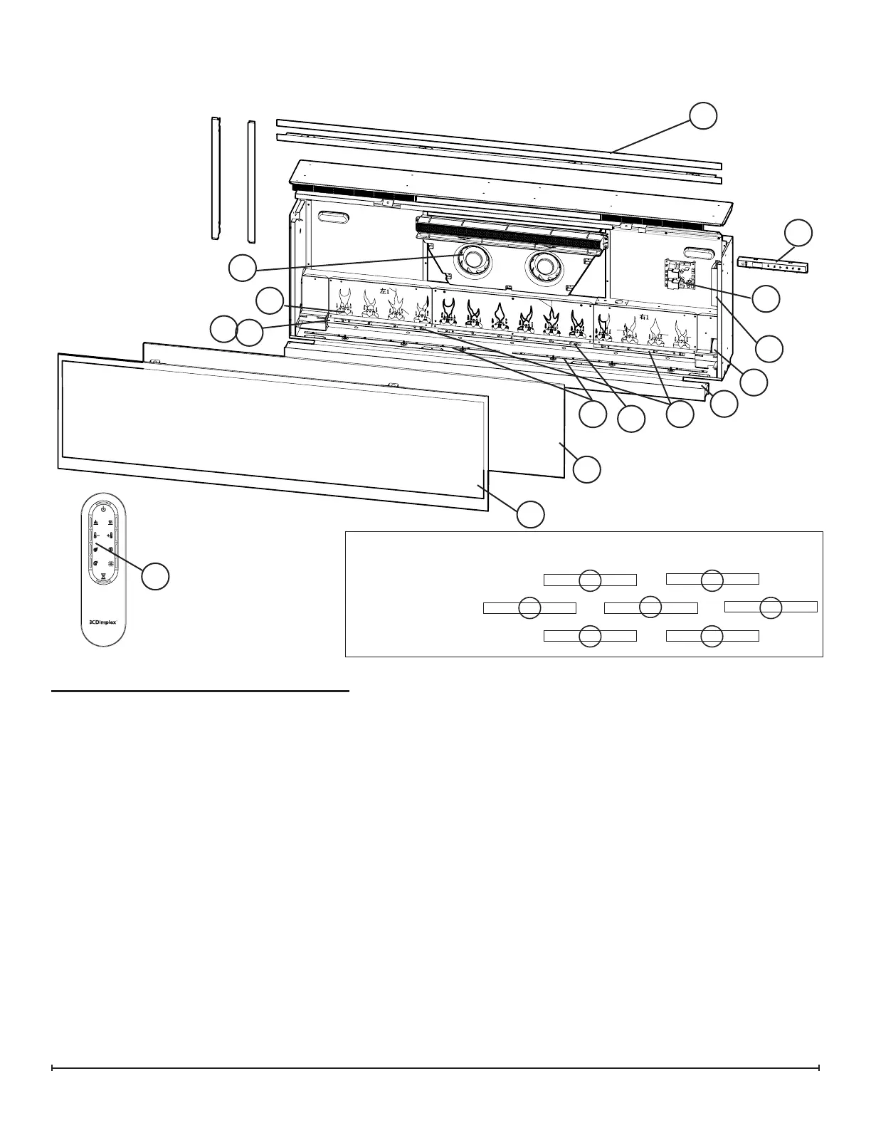
Exploded Parts Diagram - XLF50
Replacement Parts List - XLF50
12
14
1
2
3
4
10
11
7
13
8
16
9
1. Heater Assembly (with cutouts) .....2203720300RP
2. Remote Control ..................3001250100RP
3. Main Control Board ...............3001650100RP
MOD A & B ........3001650200RP
MOD C+ ............. 500002224
4. Capacitive Controls and Display .....3001680100RP
MOD A & B ........3001680200RP
MOD C+ ............ 500002215
5. Power Supply ...................2100250500RP
6. Thermistor ......................3001560500RP
7. Partially Reective Glass ..........5902890100RP
8. Front Glass .....................5902900100RP
9. Flicker Motor ....................2000500900RP
10. Flicker Assembly ................5902920100RP
11. 6-Light LED Flame Assembly .......3001760600RP
12. 8-Light LED Flame Assembly .......3001760700RP
13. Media Tray .....................5902910100RP
14. 4-Light RGB LED Assembly (2) .....3001570400RP
MOD B ...........3001960100RP
15. 6-Light RGB Media LED Assembly ...3001570100RP
MOD B ...........3001960300RP
16. 8-Light RGB Media LED Assembly (2) 3001570300RP
MOD B ...........3001960400RP
17. Mounting Hardware Kit ............9600350100RP
18. Large Acrylic Media ...............1400130200RP
19. Medium Acrylic Media .............1400150100RP
20. 4-piece Trim ....................9602160100RP
21. Front Glass Screws ...............8099770100RP
22. Screw Covers (MOD B) ...........0442370100RP
23. Power Cord (MOD B) .............4100360100RP
24. Flicker Assembly Bushing ........ x-8500680100RP
15
5
20
11
15
14
LED Conguration
Flame LED’s (white)
Flame Base (colour)
Media (colour)
12
16 16
14