www.dimplex.de 452172.66.10-EN · FD 0311 EN-9
LIA 0608BWCF M - LIA 1316BWCF M English
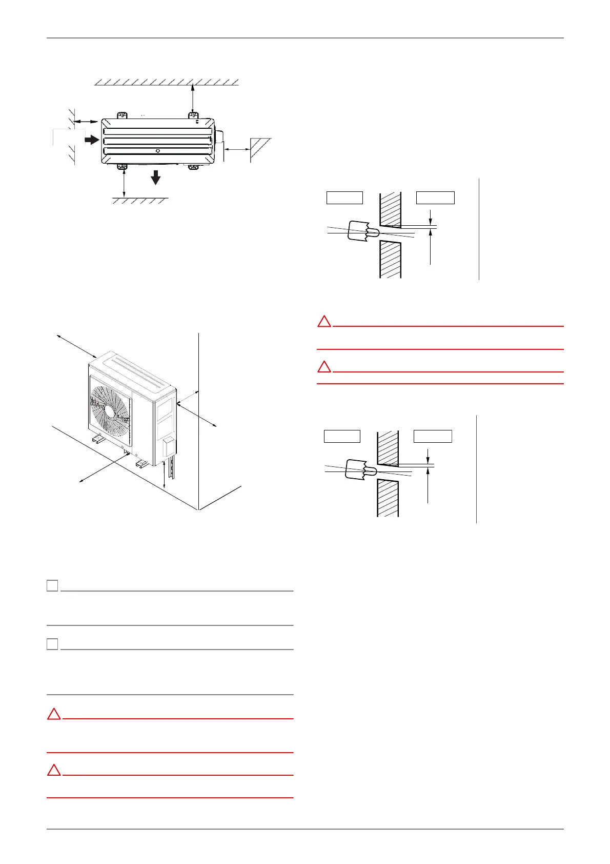
Abb. 5.4
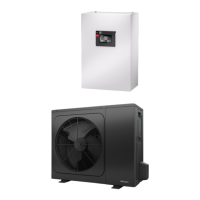
If the unit is installed on a wall bracket, special attention must
be paid to separate any sound to the building.
If the wall bracket installation option is selected, the following
points must be observed:
Fit rubber buffers
Take the weight of the outdoor unit into account
Ensure that the wall bracket is no higher than 1 m above
the ground
Ensure that minimum clearances are adhered to
Abb. 5.5
When installing several outdoor units next to each other, the
specified distances must be observed. Furthermore, if several
outdoor units are installed, it must be ensured that the air inlets
and outlets do not affect any of the other units.
º
Structural influences must be observed for installation close
to walls. No windows or doors should be present in the area
surrounding the air outlet of the fan.
º
Installation in a hollow or in an inner courtyard is not
permitted because cooled air collects at ground level and is
drawn in again by the heat pump during extended periods of
operation.
!
Incorrect installation, maintenance or repair may increase the
risk of cracks in the installed piping, resulting in property
damage.
Improper installation of the unit may restrict operation of the
system.
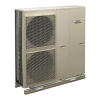
5.2.1 Wall opening, split lines and electric
wires
Please proceed as follows when laying split lines and electric
wires:
Drill a 70 mm opening for the pipework using a core drill.
The opening for the pipework should be slightly inclined
towards the outdoor unit, so that no rainwater can pene-
trate the building.
During installation work, please ensure that connection points
are easily accessible for maintenance and repair purposes.
!
Care must be taken to ensure that the connections and lines
are not subjected to any mechanical loads.
!
Connection lines must not exhibit any mechanical damage.
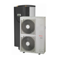
5.2.2 Wall opening for condensate drain
For the safe drainage of the condensate, the condensate drain
must be positioned in such a way that no frost build-up can oc-
cur. The frost line can vary according to the climatic region. The
regulations of the countries in question must be observed.
When laying the condensate connection, pay attention to the
slope that must be maintained.
>600
>300
Air inlet
>300
2000
Air outlet
Maintenance
area
Air inlet
1,5 m1,5 m
1,5 m1,5
m
2 m2 m
0,0,
3 m
0,0,
3 m
:DOO
5~7mm
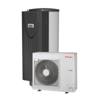
Indoor unit Outdoor unit
aPP
Wall
Indoor unit
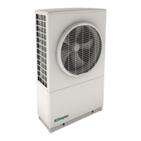
Outdoor unit