EN-8 452172.66.10-EN · FD 0311 www.dimplex.de
English LIA 0608BWCF M - LIA 1316BWCF M
!
The device must not be installed or operated near a naked
flame, gas-powered devices, electric heaters or any other
comparable source of ignition.
!
The unit must not be installed in a room that is also used as a
workplace or workshop (risk of ignition due to flying sparks).
When installing the unit, make sure that no ventilation
openings are blocked.
º
The heat pump is not intended for use above 2000 metres
(mean sea level).
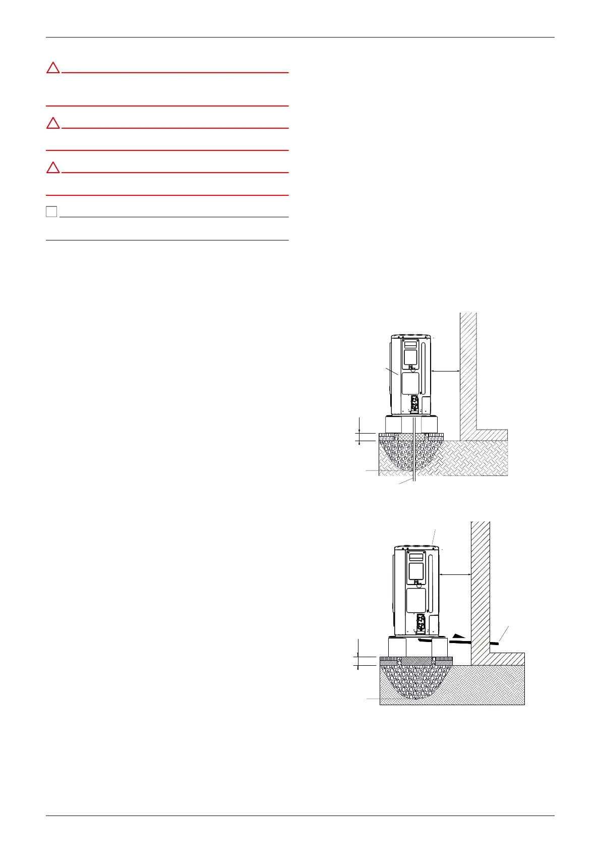
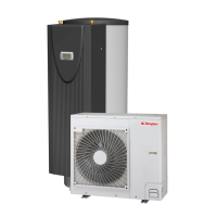
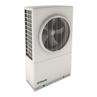
5.2 Outdoor unit
It is advisable to install the outdoor unit close to a wall, on a
foundation separate from the building with a minimum
clearance of 0.3 m on the intake side (Fig. 5.2 + Fig. 5.3).
If a canopy is mounted to protect from direct sunlight, rain
or snow it must not impede the heat exchange of the unit.
In the case of a free-standing installation, the foundation is
to be connected on the intake side, flush with the unit. This
will prevent snow from building up between the foundation
and the evaporator.
The minimum clearances (Fig. 5.2) indicated must be ad-
hered to.
When selecting an installation location, it should be en-
sured where possible that persons are not going to be in-
convenienced by the circulation of warm/cold air or by
noise emissions.
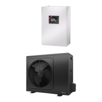
The condensate tray offers various options for condensate
draining. In warmer regions, the condensate can drain from
the device freely. In regions with longer periods of frost,
controlled condensate draining is required.
Abb. 5.2
Abb. 5.3
0,2 m
0,3 m
Heat pump
Condensate drain
Frost line
0,3 m
0,2 m
> 5%
Heat pump
Condensate drain
Frost line