www.dimplex.de 452172.66.10-EN · FD 0311 EN-21
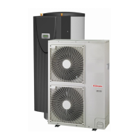
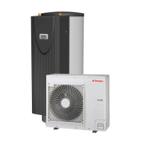
LIA 0608BWCF M - LIA 1316BWCF M English
Connecting electronically regulated circulating
pumps
Electronically regulated circulating pumps may have high start-
ing currents, which may reduce the service life of the heat
pump manager. If the starting current value is high, or is un-
known, install a coupling relay. The coupling relay must be sup-
plied by the customer. This is not necessary if the maximum
permissible operating current of the heat pump manager (see
specifications in the electrical documentation) is not exceeded
by the electronically regulated circulating pump or a relevant
approval has been issued by the pump manufacturer.
The high-efficiency pumps (UPH) are supplied with the
relevant coupling relay for connecting and operating the
electronically regulated circulating pump.
!
It is not permitted to connect more than one electronically
regulated circulating pump via a single relay output.
7.2.3 Frost protection
Regardless of the settings for the heat circulating pumps, they
always run in heating, defrost and frost protection mode. In sys-
tems with multiple heating circuits, the 2nd and 3rd heat circu-
lating pump has the same function.
!
To ensure that the frost protection function on the heat pump
works properly, the heat pump manager must remain
connected to the power supply and flow must be maintained
through the heat pump at all times.
!
The primary pump (M11 – responsible for the heat source flow
rate) and the secondary pump (M16 – responsible for the
warm/cold water flow rate) must always be clamped to the
heat pump manager in all cases. This is the only way to ensure
the pump flows and returns necessary for operation and to
ensure that the necessary safety measures are in place.
7.3 Final work
Once the pipes and electric cables have been connected, the
pipes must be bent and a leak test must be carried out. The leak
test must be carried out with particular care, as a refrigerant
leak results in a direct reduction in output.
Leaks are also difficult to identify once the installation is com-
plete.
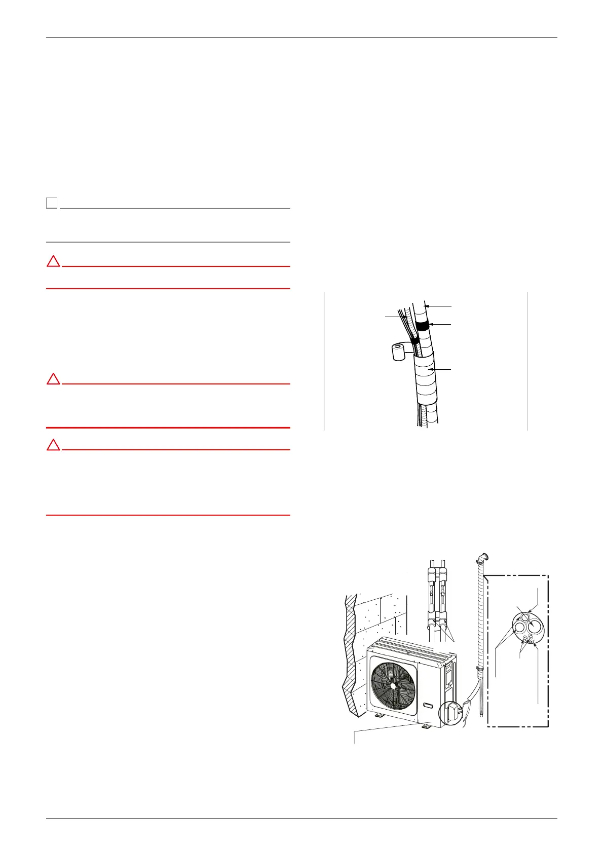
7.3.1 Pipe bends
Bend the pipes by covering the connection cable and refriger-
ant pipe (between the indoor and outdoor unit) with insulation
and fix the insulation in place with two adhesive tapes.
1) Fix the refrigerant pipe, mains cable and connection cable
with adhesive tape from bottom to top. Fix the bound pipe-
work along the wall.
2) Form a siphon to prevent water from entering the chamber
and electrical components.
3) Fix the pipework to the wall using clamps or similar.
Wrap the pipework in adhesive tape
1) Fix the pipes, mains cable and connection cable with adhe-
sive tape from bottom to top. If they are fixed from top to
bottom, rain could enter into the pipes or cables.
2) Fix the bound pipework along the external wall with clamps
or similar.
3) A siphon prevents water from entering the electrics.
'UDLQKRVH
QRWXVHG
Adhesive tape
(narrow)
Pipe
Wrapped in
adhesive tape
(wide)
A siphon prevents water from entering the electrics
Adhesive tape
Drain hose
(not used)
Refrigerant pipes
Connection cable
Mains cable
Seal a small
opening around
the pipings with
gum type sealer.
Seal small gaps
around the pipe,
e.g. with silicon.
KlebebandAdhesive tape