EN-16 452172.66.10-EN · FD 0311 www.dimplex.de
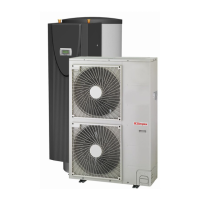
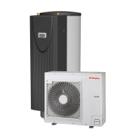
English LIA 0608BWCF M - LIA 1316BWCF M
Hot water outlet
The hot water outlet connection supplies domestic hot water
through the entire building and must be distributed to different
water-consuming outlets as required.
The connection on the indoor unit is a 1 inch external thread
pipe connection.
The domestic hot water cylinder is also equipped with a 3/4
inch internal thread connection for the circulation pipe.
!
Pipe runs should be made as short as possible and oversizing
should be avoided. All pipework should be laid in accordance
with legal requirements to prevent heat loss from the system
and avoid the build up of condensate.
A corresponding purging facility must also be implemented on-
site in the heating circuit.
It is advisable to fit a shut-off device in the return before inte-
grating the indoor unit.
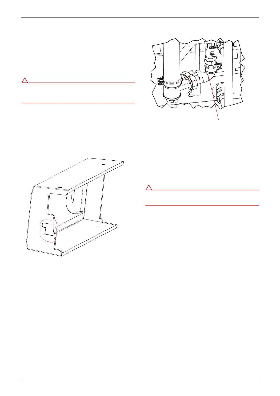
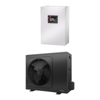
Connecting a second (external) heat generator
To integrate a second (external) heat generator in the heating
water circuit, it is necessary to cut out the thinned material area
underneath the unit cover.
The copper pipe link cable (in the flow direction) before the
electric heating must also be removed. If the electric heating is
to remain in the heating water circuit, the radiator must be
turned approximately 18° -20° towards the cylinder. This is
necessary to ensure that connection can take place without ob-
struction (with pipe bend 28 and cap nut).
approx. 18° - 20°
If the electric heating is to be removed from the heating circuit,
the heating pipes are connected directly to the thread connec-
tions 1 1/4" with a flat sealing connection. In this case, the con-
nected flow pipe should be fixed in the area where the radiator
mounting used to be (weld-free and secure).
Minimum heating water flow rate
The minimum heating water flow rate through the heat pump
must be assured in all operating statuses of the heating system.
!
If the minimum heating water flow rate is undershot, the plate
heat exchanger in the refrigeration circuit can freeze, which
can lead to total damage of the heat pump.
The nominal flow rate is specified depending on the max. flow
temperature in the device information and must be taken into
account during planning. With design temperatures below
30 °C in the flow, the design must be based on the max. volume
flow with 5 K spread for A7/W35.
The specified nominal flow rate (see “Device information” on
page 31.) must be assured in all operating states. A built-in flow
rate sensor is used only for switching off the heat pump in the
event of an unusual and abrupt drop in the heating water flow
rate and not for monitoring and fusing the nominal flow rate.
Frost protection
If the indoor unit is installed where there is a risk of frost, manual
drainage must be provided where required. The frost protection
function of the heat pump manager is active whenever the heat
pump manager and the heat circulating pump are ready for op-
eration. The system must be drained if the heat pump is taken
out of service or in the event of a power failure. The hydraulic
network should be operated with suitable frost protection if
heat pump systems are implemented in buildings where a
power failure cannot be detected (e.g. holiday homes).
** approx. 18° - 20°
**