13
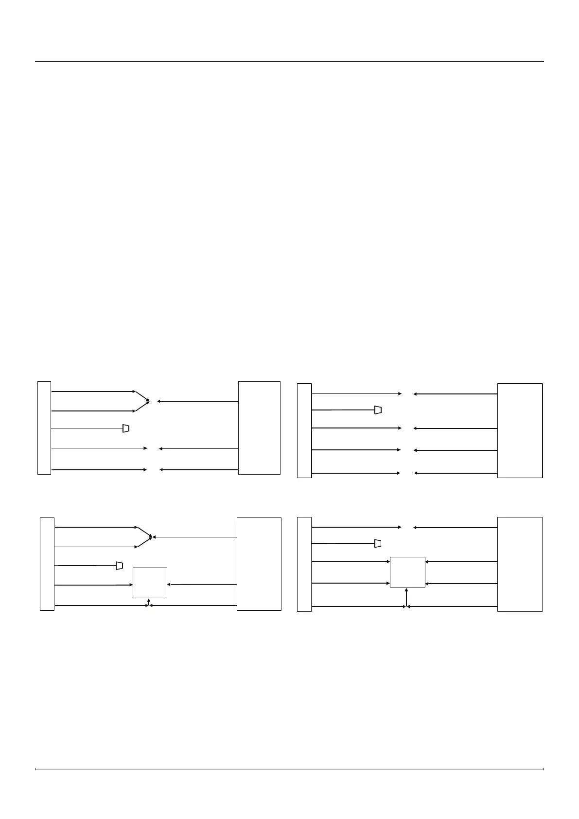
120 V Hardwire Installation
Use 2-conductor wires with ground (3 wires total) from
the power supply (breaker panel) to the junction box on
the built-in electric rebox.
1. Pull out the 5 wires marked L1, L2, N, NH, and G
(black, red, white, blue, and green).
2. Connect the white N and blue NH wires from the unit
to the neutral wire from the power supply.
3. Terminate the red L2 wire from the unit using a wire
connector (not included).
4. Connect black L1 wire from the unit to the live wire
from the power supply.
5. Connect the green G ground wire from the unit to the
ground from the power supply.
6. Insert all the wiring back into the rebox and secure
with a cable clamp (not included).
7. Make sure all connections are tight.
ACE JUNCTION BOX
WHITE - N
BLACK - L1
GROUND - G
WHITE - N
BLACK - L1
GROUND - G
120 V
POWER
SUPPLY
BREAKER
PANEL
BLUE - NH
RED - L2
120 V Hardwire InstallationFigure 10
Installation
FIREPLACE JUNCTION BOX
120 V
POWER
SUPPLY
BREAKER
PANEL
RED - L2
BLACK - L1
GROUND - G
WALL
SWITCH
BLACK - L1
GROUND - G
WHITE - N
BLUE - NH
WHITE - N
240 V Hardwire Installation
Use 3-conductor wires with ground (4 wires total) from
the power supply (breaker panel) to the junction box on
the built-in electric rebox.
1. Pull out the 5 wires marked L1, L2, N, NH, and G
(black, red, white, blue, and green).
2. Connect the white N wire from the unit to the neutral
wire from the power supply.
3. Terminate the blue NH wire with a wire connector.
4. Connect the black L1 wire from the unit to the one of
the live wires from the power supply.
5. Connect the red L2 wire from the unit to the second
live wire from the power supply.
6. Connect the green G wire from the unit to the ground
from the power supply.
7. Insert all the wiring back into the rebox and secure
with a cable clamp (not included).
8. Make sure all connections are tight.
FIREPLACE JUNCTION BOX
WHITE - N
BLACK - L1
GROUND - G
WHITE - N
BLACK - L1
GROUND - G
240 V
POWER
SUPPLY
BREAKER
PANEL
RED - L2
RED - L2
BLUE - NH
120 V Wall Switch Installation
Figure 11
Figure 12
240 V Hardwire Installation
FIREPLACE JUNCTION BOX
WHITE - N
BLACK - L1
GROUND - G
WHITE - N
BLACK - L1
GROUND - G
240 V
POWER
SUPPLY
BREAKER
PANEL
RED - L2
RED - L2
BLUE - NH
WALL
SWITCH
Figure 13
240 V Wall Switch Installation