10 www.dimplex.com
Installation
Preparing the Firebox for Installation
!
NOTE: For multi-unit installation, refer to instructions provided with the accessory
kit (XLFXDLINK, sold separately).
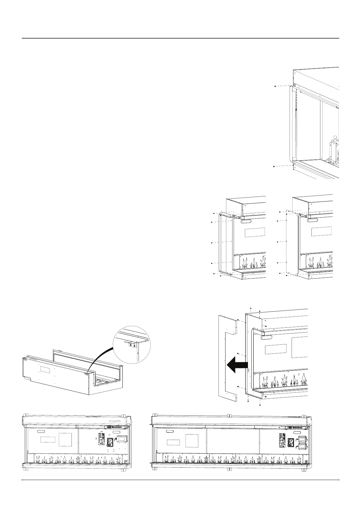
1. Remove packing support brackets by removing the 2 screws on the top and on the
1 screw on the bottom of each bracket. (Figure1) These brackets and screws can
be discarded.
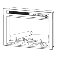
2. Install the desired side trim option on each side of the rebox. Install the side panel
using 7 black screws.
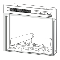
• For open sides, select the open side trim. (Figure2)
• For closed sides, install the closed side trim. (Figure3) Do not install the side glass
panels in this conguration.
• For multi-unit installations, remove side panels on adjoining sides by removing the
9 screws. (Figure4) Do not install any trim or side glass on adjoining sides.
Figure2 Figure3
Figure4
Figure5
Figure 6
Figure 7
Figure1
3. Install the optional power cord accessory if desired,
following the instructions in the Electrical Installation section
(p.15). (XLFXDPLUG, sold separately)
4. If a permanently heat-disabled installation is desired, follow
the instructions to disable the heater in the Permanent Heat
Disable section (p.16).
5. Carefully lay the rebox on its back and install the mounting
brackets to the top and bottom of the rebox with the black
screws provided. (Figure5)
!
NOTE: There are 4 mounting brackets for
XLF5017-XD and XLF6017-XD units (Figure6), and 6
mounting brackets for XLF7417-XD, XLF8817-XD and
XLF10017-XD units. (Figure7)
!
NOTE: The mounting brackets are equipped with slots to
allow small adjustments to t the framing. Ensure all the
brackets are aligned.