11
Installation Instructions
!
NOTE: Two people are required for installation.
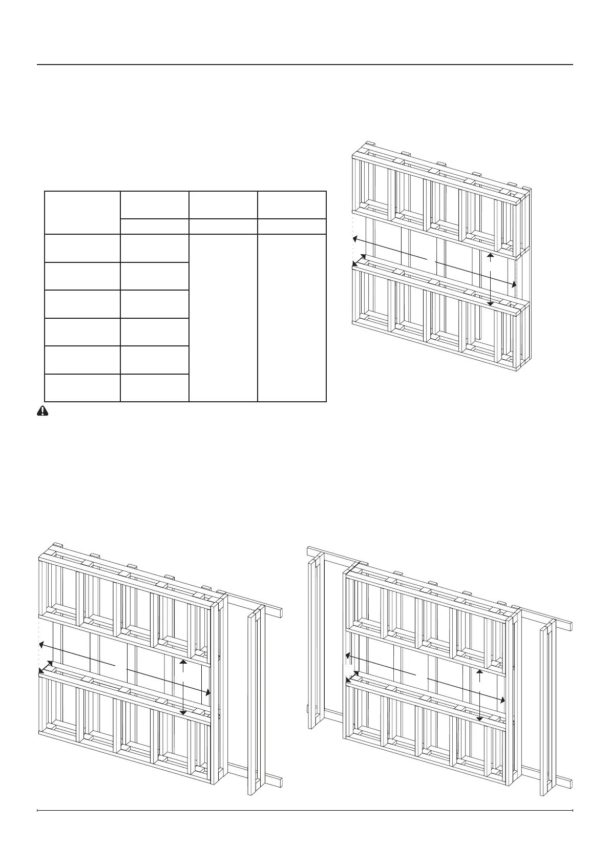
1. Prepare a wall with a framed opening, following the
dimensions in the table below. The dimensions are the same
for front, corner, and bay installations.
Framing Dimensions
Model
Width Height
Depth
(minimum)
A B C
XLF5017-XD
49 "
1257 mm
24 ¼"
616 mm
11 "
295 mm
XLF6017-XD
62 ¼"
1581 mm
XLF7417-XD
"
1895 mm
XLF8817-XD
87
3
16
"
2215 mm
XLF10017-XD
"
2534 mm
Custom
Length
Add widths
of units used
CAUTION: This replace is NOT load-bearing. Ensure the
opening for the replace is framed in such a way that the
weight of the building materials will not create pressure on
the top of the replace.
!
NOTE: Wiring is located at the top right back corner of the
rebox. Plan the framing to allow routing the power cable to
this location.
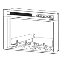
Front Installation
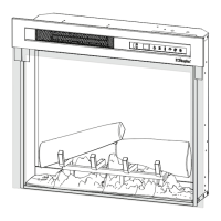
Left/Right Corner Installation
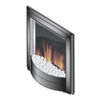
Bay Installation
Figure 8
Figure 9
Figure 10
Installation
A
B
C
C
A
B
A
B
C