15
Optional Plug Kit (XLFXDPLUG, sold separately)
WARNING: Power cord option is only suitable for 120V installations.
1. Remove the 3 screws that hold the electrical cover plate.
2. Connect the black L1 wire from the unit to the black wire of the plug kit.
3. Connect the white N wire from the replace to the white wire from the plug kit.
4. Connect green G wire from the replace to the green wire from the plug kit.
5. Ensure all wire connections are tight.
6. Secure the power cord’s pre-installed cover plate using the screws removed when removing the electrical cover plate.
The previously removed electrical cover plate can be disposed of.
WARNING: This heater is not intended for use with an extension cord. Plug the cord directly into an ap propriate
wall receptacle.
120 V
POWER
SUPPLY
(BREAKER
PANEL)
240 V
POWER
SUPPLY
(BREAKER
PANEL)
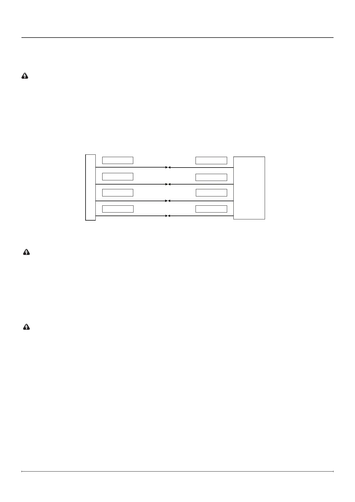
Figure 18
240V Hardwire Installation (Figure18)
You will need a 4-wire240 V supply (L1, L2, Neutral, and Ground).
WARNING: Use the appropriate wire to meet local and national electrical codes for rated power consumption.
1. Connect the black L1 wire from the unit to the L1 wire from the power supply with a wire connector.
2. Connect the red L2 wire from the unit to the L2 wire from the power supply with a wire connector.
3. Connect the white N wire from the unit to the neutral wire from the power supply.
4. Connect the green G wire from the unit to the ground wire from the power supply with a wire connector or attach the
grounding wire.
5. Ensure all wire connections are tight.
Installation