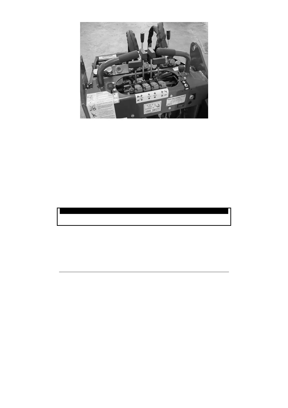
Control panel diagram
1. Drive control levers
2. Attachment tilt lever
3. Loader arms lever
4. Auxiliary hydraulic lever
5. Pump selector valve
6. Kohler engine Dingoes – Choke
Robin engine Dingoes – Throttle
Kubota engine Dingoes – position empty
7. Kohler and Kubota engine Dingoes – Throttle
Robin engine Dingoes – position empty
8. Ignition.
Auxiliary hydraulic lever
The auxiliary hydraulics lever is to allow you to alter the direction of rotation of
hydraulically driven attachments or stop them completely.
Attention
Ensure auxiliary hydraulic lever is in neutral position before starting engine. Aside
from starting difficulties the attachment may move during starting.
To operate attachment in forward direction, slowly pull auxiliary lever rearward.
To operate attachment in reverse direction, slowly push auxiliary lever forward.
Pump selector valve
When faster ground speed and lifting speed is required more than attachment speed
and power, push the pump selector lever to the full forward position (hare).
When faster attachment speed and power is required more than ground speed and
lifting speed, pull pump selector lever to the full rearward position (turtle).
Dingo 950 Operation & Maintenance Manual
16