15
5.2. Wall mounting of the salt chlorinator control box
1) Fix the support to the wall with the screws and plugs provided.
2) Slide the box on the support from top to bottom.
5.3. Installation of the flow controller
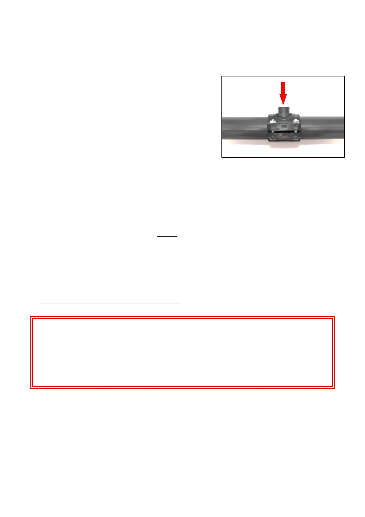
1) Mount the support collar 6 on the pipes such as on the photo opposite.
2) Drill the top of the pipe through the orifice of the support collar (see
arrow opposite) by taking care not to damage the tapping.
3) Remove the protection from the flow controller 7.
4) Screw and tighten the flow controller 7 into the support collar 6. Position
it so that the arrow on the controller is in the flow direction.
5.4. Installation of the online cell
1) If the pipe has an outside diameter of 50 mm, cut the pipe to a length of 316 mm.
1) If the pipe has an outside diameter of 63 mm, cut the pipe to a length of 296 mm.
2) Remove the nuts and ball joints from the cell.
3) Pass sandpaper on all surfaces to be glued: pipes, reducers (if 50mm pipe), ball joints.
4) Slide each nut onto each pipe.
5) Glue each set (pipe – reducer – ball joint).
6) Wait until the collages are completely dry.
7) Place each seal at the ends of the cell.
8) Fix the cell with 2 nuts. Screw and tighten the nuts by hand.
5.5. Electrical connections
All cables listed below are fitted at the factory to the box and marked at the end.
1) Connection of the box power cable (230V – 50Hz):
I Connect the box permanently to a power supply board.
H
Before connecting of the power cable to the box, ensure that the electrical installation complies with the
existing standards and regulations in the country of installation.
The connection must be made by a qualified electrician.
Cut off the power supply at the circuit breaker beforehand and make sure the power supply is switched off
with the appropriate tools.