2
© 2011 Directed Electronics. All rights reserved.
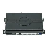
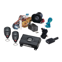
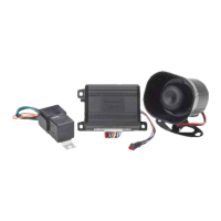
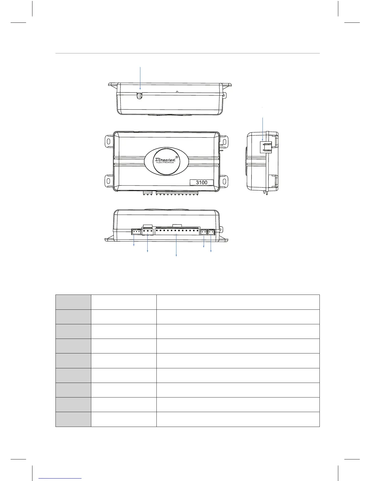
Wiring Connections
12-pin Primary Harness
3-pin Horn Honk Harness
Door Lock port
Status LED port
Valet button port
Starter interrupt input/output
Impact sensor adjuster
Main Harness 12-pin Connector (H1)
H1/1 ORANGE (-) 500 mA Ground-When-Armed Output
H1/2 WHITE (+/-) Selectable Light Flash Output
H1/3 WHITE/BLUE (-) 200 mA Channel 3 Validity Output
H1/4 BLACK/WHITE (-) 200 mA Interior Light Illumination Output
H1/5 GREEN (-) Door Trigger Input, Zone 3
H1/6 BLUE (-) Multiplex Trigger Input, Zone 1
H1/7 VIOLET (+) Door Trigger Input, Zone 3
H1/8 BLACK (-) Chassis Ground Input
H1/9 YELLOW (+) Ignition Input, Zone 5