5
403.VW08 1.35 2020 Audi Q7 (Smart Key)
©2021 VOXX•DEI LLC. All rights reserved.
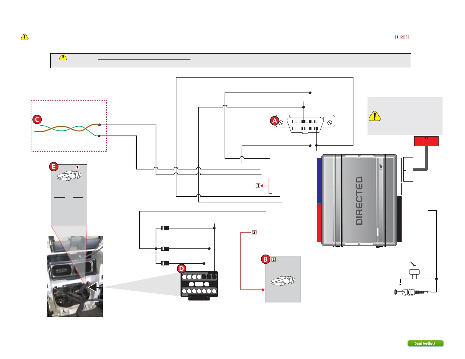
Refer to "Pre-installation and application warnings" for important information, such as the description of each special note referenced in the diagram ( ).
Wiring diagram
Key Wrap: Orange/Red: 10
HS CAN 3 High: Orange/Green: 5
HS CAN 3 Low: Orange/Brown: 6
Key Wrap: Yellow/Red: 11
Key Wrap: Brown/Red 12
(+) 12V Input: Red: 13
(-) Ground: Black: 14
HS CAN 1 Low: Tan: 4
(-) PTS Output: Green/Black: 2
(+) Brake Activation Output: Gray: 6
HS CAN 1 High: Tan/Black: 3
6: White/Black:
(-) Hood Input
Remote Start Safety
Override Switch
Hood Pin
Note: hood pin only
required on vehicles not
equipped with a factory
hood pin.
You can connect to either a
XL202 RFTD OR a SmartStart
module.
Refer to the SmartStart/XL202
Installation Notes for more
information.
16
8
9
1
OBDII
Diagnostic
Connector
HS CAN 1 Low: Violet/Brown,pin 14
HS CAN 1 High: Blue/Green, pin 6
There are two possible installation methods for this vehicle. The alternative wiring diagram and information can be found
following this method. Choose the one that is more convenient and for all other info, refer to Vehicle connections.
See Vehicle
connections for
more information.
14
7
13
6
12
5
11
4
10
3
9
2
8
1
15
16
17
Black Connector
(rear of center console)
(-) PTS 6:
Blue/Yellow, pin 3
(-) PTS 5:
White/Gray, pin 2
(-) PTS 4:
Yellow/Gray, pin 1
(+) 12V:
Red, pin 16
3X Diode 1A
Twisted pair
(in driver kick, door harness)
Alternative: HS CAN 3 wires
HS CAN 3 High: Green
HS CAN 3 Low: Orange/Brown
(-) Ground: Brown, pin 4
See Vehicle
connections for
more information.
Immo.
Remove the
cloth tape
for the twisted
Yellow and White
Immo. wires.
(+) Brake
Black/Red wire
in driver’s firewall
harness.