6
403.VW08 1.35 2020 Audi Q7 (Smart Key)
©2021 VOXX•DEI LLC. All rights reserved.
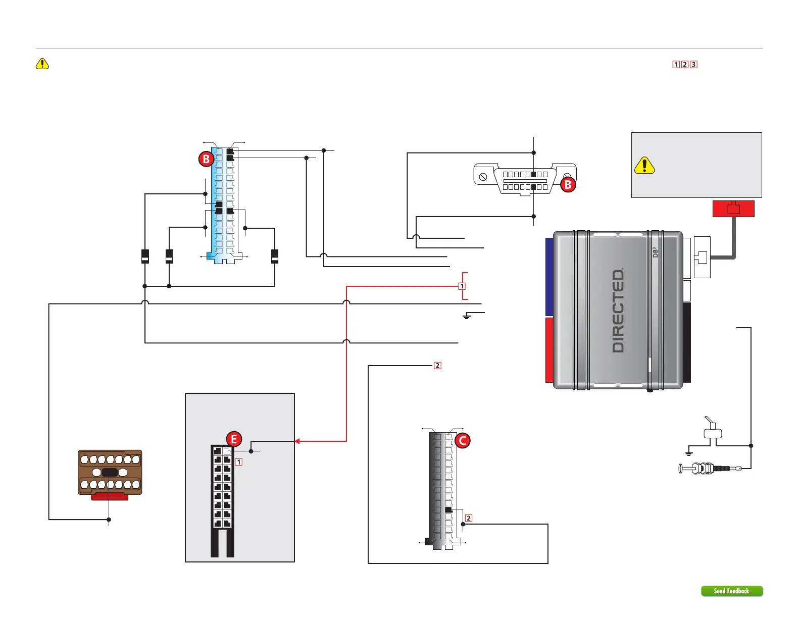
Refer to "Pre-installation and application warnings" for important information, such as the description of each special note referenced in the diagram ( ).
Wiring diagram (alternative installation)
Key Wrap: Orange/Red: 10
HS CAN 2 High: Orange/Green: 5
HS CAN 2 Low: Orange/Brown: 6
Key Wrap: Yellow/Red: 11
Key Wrap: Brown/Red 12
(+) 12V Input: Red: 13
(-) Ground: Black: 14
HS CAN 1 Low: Tan: 4
(-) PTS Output: Green/Black: 2
(+) Brake Activation Output: Gray: 6
HS CAN 1 High: Tan/Black: 3
6: White/Black:
(-) Hood Input
Remote Start Safety
Override Switch
Hood Pin
Note: hood pin only
required on vehicles not
equipped with a factory
hood pin.
You can connect to either a
XL202 RFTD OR a SmartStart
module.
Refer to the SmartStart/XL202
Installation Notes for more
information.
16
8
9
1
OBDII
Diagnostic
Connector
HS CAN 2 High:
Green, pin 2
(-) PTS 3:
Blue/Yellow,
pin 10
(-) PTS 1:
Yellow/Gray,
pin 25
(-) PTS 2:
White/Gray,
pin 26
HS CAN 2 Low:
Orange/Brown, pin 1
(+) 12V:
Red/Yellow,pin 16
HS CAN 1 Low: Violet/Brown,pin 14
HS CAN 1 High: Blue/Green, pin 6
Comfort System Module
(brown conn.
in left rear quarter panel,
below fuse box)
Comfort System Module
(black/white conn.
in left rear quarter panel,
below fuse box)
14
7
13
6
12
5
11
4
10
3
9
2
8
1
15 16 17
Comfort System Module
(blue/white conn.
in left rear quarter panel,
below fuse box)
1
16
17
32
1
16
17
32
Comfort System Module
(black conn.
in left rear quarter panel,
below fuse box)
Diode 1A
Diode 1A
Diode 1A
(+) Brake: Black/Red, pin 12
IMMO Antenna:
Yellow, pin 11
11