40
DS4+ FORD6
© 2017-12-13 Directed. All rights reserved.
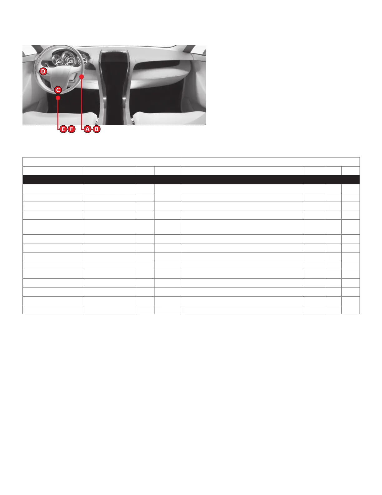
Vehicle wiring reference chart
This section provides vehicle wiring information to guide you through the various stages of your installation. Refer to
www.directechs.com for additional information.
Wire Information Connector Information
Function Color Pin Polarity Location Color Pins Ref.
Ford Transit Connect (without power locks) 2010-2013
12V - With T-harness Red 2 Data Drivers dash fuse box. White 2 F
RX White/Lt. Green 4 Data (PATS) connector. Black 4 A
TX Gray/Orange 3 Data (PATS) connector. Black 4 A
12V - Without T-harness Red 4 (+) Ignition switch. Black 7 B
Starter Gray/Black or
Orange/Black
7 (+) Ignition switch. Black 7 B
Ignition Green/Yellow 1 (+) Ignition switch. Black 7 B
Accessory Yellow 6 (+) Ignition switch. Black 7 B
Parking Lights Orange/Yellow 13 (+) Headlight switch. Black 16 D
HS CAN High Gray/Red 6 Data OBDII. Black 16 C
HS CAN Low Blue/Red 14 Data OBDII. Black 16 C
MS CAN High Gray/Orange 3 Data OBDII. Black 16 C
MS CAN Low Blue/Black 11 Data OBDII. Black 16 C
Driver Door Trigger Black/Yellow 18 (-) GEM (Generic Electronic Module) behind dash fuse box. Gray 23 E
Tach NOT White/Red N/A (AC) Any fuel injector. N/A N/A N/A