EasyManua.ls Logo

Directed DS4 Plus - User Manual

Directed DS4 Plus
44 pages
Print Icon
To Next Page IconTo Next Page
Loading...
VW10
INSTALLATION GUIDE
This product is intended for installation by a professional installer only! Attempts to install this
product by a person other than a trained professional may result in severe damage to a vehicle’s
electrical system and components.
2017-11- 02
© 2017 Directed, Vista CA
DS4+
Designed by Installers for Installers

Questions and Answers

  • K
    kevinfoleyAug 20, 2025
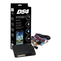
    How to troubleshoot Directed DS4 Plus Car Alarm module with no power?
    • K
      Kimberly SextonAug 20, 2025
      If your Directed Car Alarm module isn't getting power, ensure the D2D harness is properly connected and that there's 12V between the red and black wires. If the voltage is correct, the module might be defective.
  • T
    Tommy ThompsonAug 22, 2025
    What to do if Directed DS4 Plus Car Alarm bypass data is not detected?
    • I
      iestesAug 22, 2025
      If your Directed Car Alarm system shows that bypass data isn't being detected, check the connection of the bypass line. If there's more than one wire, ensure they aren't inverted. Also, confirm that the vehicle still functions correctly with the factory key.
  • W
    Whitney DaltonAug 25, 2025
    What to do if Directed DS4 Plus CAN1 is not detected?
    • T
      troydavidsonAug 25, 2025
      If your Directed Car Alarm system indicates that CAN1 isn't being detected, check the connections of the Tan and Tan/Black wires. Try waking up the data bus by turning the ignition on and trying again. If your setup doesn't need this connection, you can skip this step by pressing the programming button 5 times.
  • J
    johnsonjeffreyAug 26, 2025
    What to do if Directed DS4 Plus Car Alarm CAN2 is not detected?
    • J
      Jason OdomAug 27, 2025
      If your Directed Car Alarm system indicates that CAN2 isn't being detected, check the Orange/Green and Orange/Brown wire connections. Try waking up the data bus by turning the ignition on and trying again. If your installation does not require this connection, skip this step by pressing the programming button 5 times.
  • N
    Nicole CollinsAug 28, 2025
    What to do if Directed Car Alarm J1850 is not detected?
    • J
      John DavisAug 28, 2025
      If your Directed Car Alarm system reports that J1850 isn't detected, check the J1850 wire connection. Then, wake up the data bus by turning the ignition on and try again.
  • S
    Shannon TaylorAug 30, 2025
    Why is my Directed DS4 Plus Car Alarm waiting to begin the programming sequence?
    • M
      Mark CareyAug 30, 2025
      If your Directed Car Alarm is stuck waiting to begin the programming sequence, make sure you're following the correct programming procedure.
  • K
    Kristen CruzSep 1, 2025
    What to do if Directed DS4 Plus Car Alarm initialization failed?
    • R
      raymondshortSep 1, 2025
      If the initialization of your Directed Car Alarm failed, reset the module and try the programming process again. Should the issue persist, further assistance is needed.
  • B
    Brandon FordSep 2, 2025
    What does it mean if Runsafe was not disabled on Directed DS4 Plus Car Alarm?
    • F
      Frank GaySep 2, 2025
      If 'Runsafe was not disabled' message appears on your Directed Car Alarm, it means that no UNLOCK command was received before the door was opened, or the 45-second timer expired in takeover mode.
  • J
    Jordan TorresSep 4, 2025
    Why is the smart key not detected by my Directed DS4 Plus Car Alarm?
    • C
      Cheryl MurraySep 4, 2025
      The smart key was not detected, which prevents the Directed Car Alarm system from shutting down the vehicle.
  • M
    mary05Sep 6, 2025
    Why are the brakes not detected by my Directed Car Alarm?
    • S
      Samuel AndrewsSep 6, 2025
      The brakes were not detected by your Directed Car Alarm, which prevents the system from shutting down the vehicle.

Summary

Installation Guide

Warning! Safety First

Critical safety guidelines for installation and operation of the system.

Introduction

Overview of the VW10 firmware for DS4+ and its compatibility.

Pre-installation and Application Warnings

Essential warnings and preparation steps before installation.

Vehicle Application Guide

Table listing compatible vehicles and required installation types.

Wiring Connections

Details for main, relay, data, analog, RF, D2D, and sensor harnesses.

Main Harness (H1) Pinout

Pinout and function of the 12-pin black main harness.

Relay Harness (H2) Pinout

Pinout and function of the 10-pin white relay harness.

Data Harness (H3) Pinout

Pinout and function of the 8-pin white data harness.

Analog Input;Output Harness (H4) Pinout

Pinout and function of the 22-pin white analog harness.

RF Port Harness (H5) Pinout

Pinout and function of the 2-pin white RF port harness.

D2 D Harness (H6) Pinout

Pinout and function of the 4-pin D2D harness.

Temperature Sensor Harness (H7) Pinout

Pinout and function of the 2-pin black sensor harness.

Installation Types and Diagrams

Comprehensive installation types with diagrams and fuse selection.

Type 1 Installation

Wiring diagram and fuse selection for Type 1 installation.

Type 2 Installation

Wiring diagram and fuse selection for Type 2 installation.

Type 3 Installation

Wiring diagram and fuse selection for Type 3 installation.

Type 4 Installation

Wiring diagram and fuse selection for Type 4 installation.

Type 5 Installation

Wiring diagram and fuse selection for Type 5 installation.

Type 6 Installation

Wiring diagram and fuse selection for Type 6 installation.

Type 7 Installation

Wiring diagram and fuse selection for Type 7 installation.

Type 8 Installation

Wiring diagram and fuse selection for Type 8 installation.

Type 9 Installation

Wiring diagram and fuse selection for Type 9 installation.

Type 10 Installation

Wiring diagram and fuse selection for Type 10 installation.

Type 11 Installation

Wiring diagram and fuse selection for Type 11 installation.

Vehicle Wiring Reference Charts

Detailed wiring data for various Volkswagen and Audi models.

Immobilizer Interface Methods

Methods for integrating the immobilizer using key wrap or OEM receiver.

Method 1: Key Wrap

Instructions for creating and placing loops around the vehicle's key.

Method 2: Immobilizer Interface with 556 U

Procedure for using the 556U interface with a regular key.

Method 3: Immobilizer Interface with OEM Receiver

Steps for connecting to the vehicle's OEM immobilizer receiver.

Module Connection and System Setup

Flashing, additional connections, RF systems, sensors, and SmartStart integration.

Flashing Module via Computer

Steps for flashing the module using the XKLoader2 and online tool.

Flashing Module via Smartphone;Tablet

Steps for flashing the module using the XKLoader3 and mobile app.

Additional Manual Transmission Connections

Required connections for manual transmission vehicles not supported by firmware.

RF Systems Overview

Information on RF systems, remotes, and control centers.

8504 D Combo Sensor Pairing

Procedure for pairing the 8504D Combo Sensor with the device.

SmartStart Compatibility and D2 D Configuration

Enabling D2D communication with SmartStart and configuring D2D ports.

Module Programming

Step-by-step guide for programming the DS4+ module.

Module Programming Sequence

Detailed steps for connecting harnesses and programming the module.

Pairing Remotes

Instructions for pairing aftermarket or factory remotes.

LED Diagnostics and Troubleshooting

Interpreting LED indicators for module programming and error codes.

Module Programming Status LEDs

Troubleshooting common LED states during module programming.

Module Programming Error Codes

Diagnosing and resolving error codes indicated by LED flashes.

Active Ground When Running Status

Understanding LED status for ground when running.

Command Status LEDs

Interpreting LED indications for various commands like lock, unlock, etc.

Shutdown Code LED Indicators

Troubleshooting system shutdown codes indicated by LED signals.

Analog Error Codes

Diagnosing feature configuration file mismatches.

Module Reset Procedures

Steps for performing soft and hard resets on the module.

Soft Reset Procedure

Erasing programming steps without affecting firmware.

Hard Reset Procedure

Reverting the module to default factory settings.

Tachometer Learning and Initialization

Procedures for learning tachometer signals and initializing Virtual Tach.

Learning the Tach Signal

Adjusting or storing the tachometer value for engine RPM detection.

Initializing Virtual Tach

Programming Virtual Tach for starter motor engagement.

Limited Lifetime Consumer Warranty

Details of the warranty coverage, terms, and conditions.

Quick Reference Guide

Summary of common commands and vehicle takeover procedures.

Sending Commands to Vehicle

Ways to send remote start, lock/unlock, and trunk commands.

Vehicle Takeover with Regular Key

Steps to take control of the vehicle after remote start.

List of Available Commands

Overview of buttons and their corresponding actions.

SmartStart Compatibility

Information on SmartStart compatibility and features.

Directed DS4 Plus Specifications

General IconGeneral
BrandDirected
ModelDS4 Plus
CategoryCar Alarm
LanguageEnglish

Related product manuals