29
DS4+ VW10
© 2017-11-02 Directed. All rights reserved.
Type 10
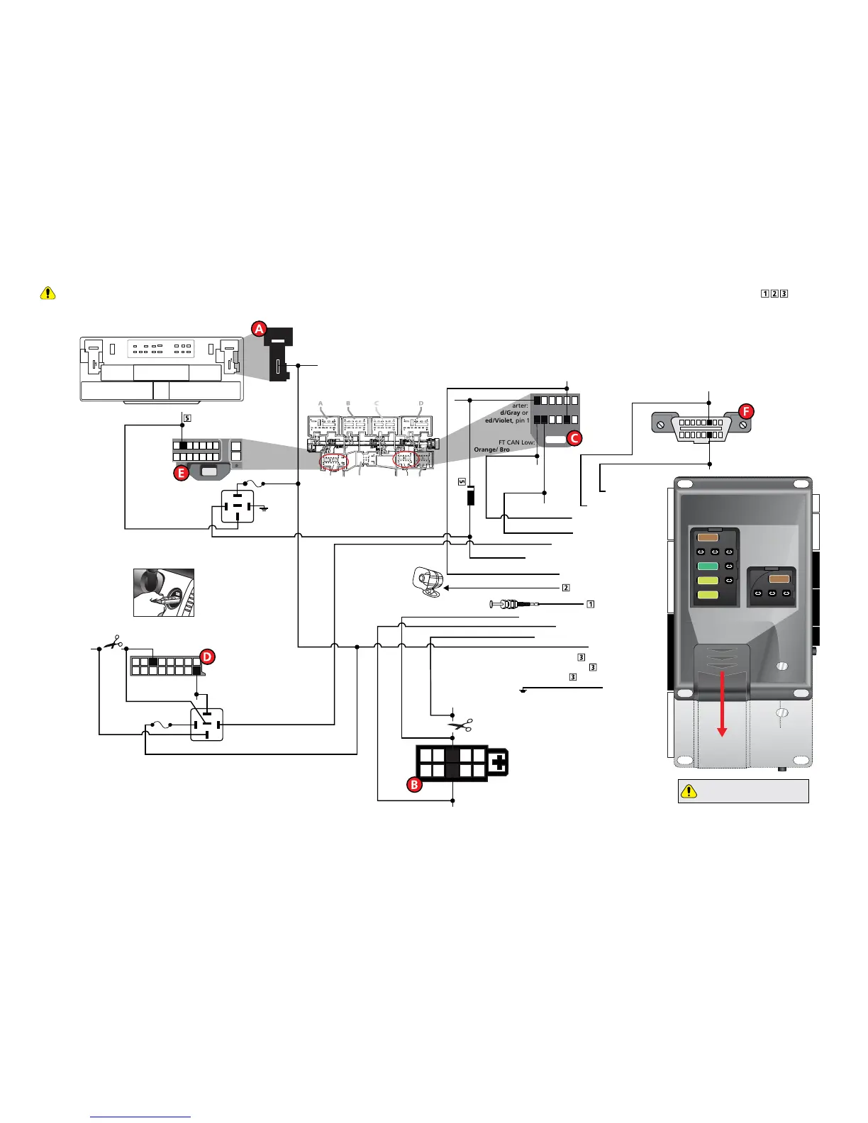
Refer to "Pre-installation and application warnings" on page 4 for important information, such as the description of special notes referenced in the diagram ( ).
16
8
9
1
Siren
Hood Pin
HS CAN High:
Orange/Black, pin 6
HS CAN Low:
Orange/Brown, pin 14
1
2
4
5
6
7
9
10
3
8
Headlight Switch
(black conn. at light switch)
CUT
Parking Light Interrupt (conn. side): Blue/White: 1
Key Wrap: Lt. Green: 8
Key Wrap: Lt. Green/White: 9
(-) Ground: Black: 10
HS CAN Low: Tan : 1
(+) Ignition Output: Violet/Black: 8
(+) Starter / Brake Activcation Output: White: 7
HS CAN High: Tan/Black: 2
FT CAN High: Orange/Green: 4
FT CAN Low: Orange/Brown: 3
(+) 12V Input: Red: 6 & 12
Key Wrap: Lt.Green/Red: 7
(-) Hood Input: Gray: 21
(+) Siren Output: Brown/Red: 11
(-) Key Release Output: Blue/White: 2
Diagnostic
Connector OBDII
(+)12V: Red/White, pin 1
(+) Brake:
Black/Red, pin 2
16
8
9
1
10
11
3
12
4
13
5
14
6
15
2 7
30
86
85
87
87a
F
H
GE
VESCM (under drivers dash)
E plug
at VESCM
(under
drivers dash)
Fuse 5A
Ignition Switch Port
(black conn. at keyport)
Ignition Switch Plug
(at Key Port)
8
16
7
15
6
14
5
13
4
12
3
11
2
10
1
9
CUT
30
86
85
87
87a
Keysense: Green,
pin 16
(+) 12V Interrupt: Green/Red, pin 3
Fuse 5A
Parking Lights Interrupt:
Red/White or Red/Black, pin 8
(+) Parking Lights: Gray/Yellow, pin 3
(+) Ignition: Red/Violet, pin 11
(+) Starter:
Red/Gray or
Red/Violet, pin 1
FT CAN Low:
Orange/ Brown,pin 7
FT CAN High:
Orange/Green,
pin 8
6542 31
12
11
10
87
G plug
at VESCM
(under drivers dash)
9
[5] Diode 1A
VESCM Connector L
(under drivers dash or behind glove box)
22
10
4
1
6
3
2
1
(+) Parking Light Output: Blue/Red: 2
Parking Light Interrupt (vehicle side): Blue: 3
DS4+
DS4
Slide
to open
Proper Fuse
Positioning
DS4+ DS4
It is important to check that the
fuses are positioned correctly.
MAIN (5A) (+)
(-) RLY3 PK LIGHT (15A) (+)
(-) ACC & START (30A) (+)
(-) FLEX RLY (20A) (+)
IGN (20A) (+)
MAIN (5A) (+)