35
DS4+ VW10
© 2017-11-02 Directed. All rights reserved.
Connecting the module
Important!
Before connecting the DS4+, it is important to ensure that the proper feature and function programming is selected using the
configuration wizard. Visit www.directechs.com to use the latest version of the online tool.
Flashing a module using your computer:
1. Disconnect the main module from any (+) 12V power source, then connect it to your computer using the XKLoader2.
2. Go to www.directechs.com using Internet Explorer; the configuration wizard will be displayed automatically.
3. Follow the instructions in the pop up window that will be displayed when the module is detected.
Flashing a module using your smartphone or tablet:
1. Disconnect the main module from any (+) 12V power source, then connect it to the XKLoader3.
2. Launch the Directechs Mobile app on your smartphone or tablet.
3. Select FLASH YOUR MODULE and follow the on-screen instructions.
When the flashing operation is successful, you can proceed with the instructions below.
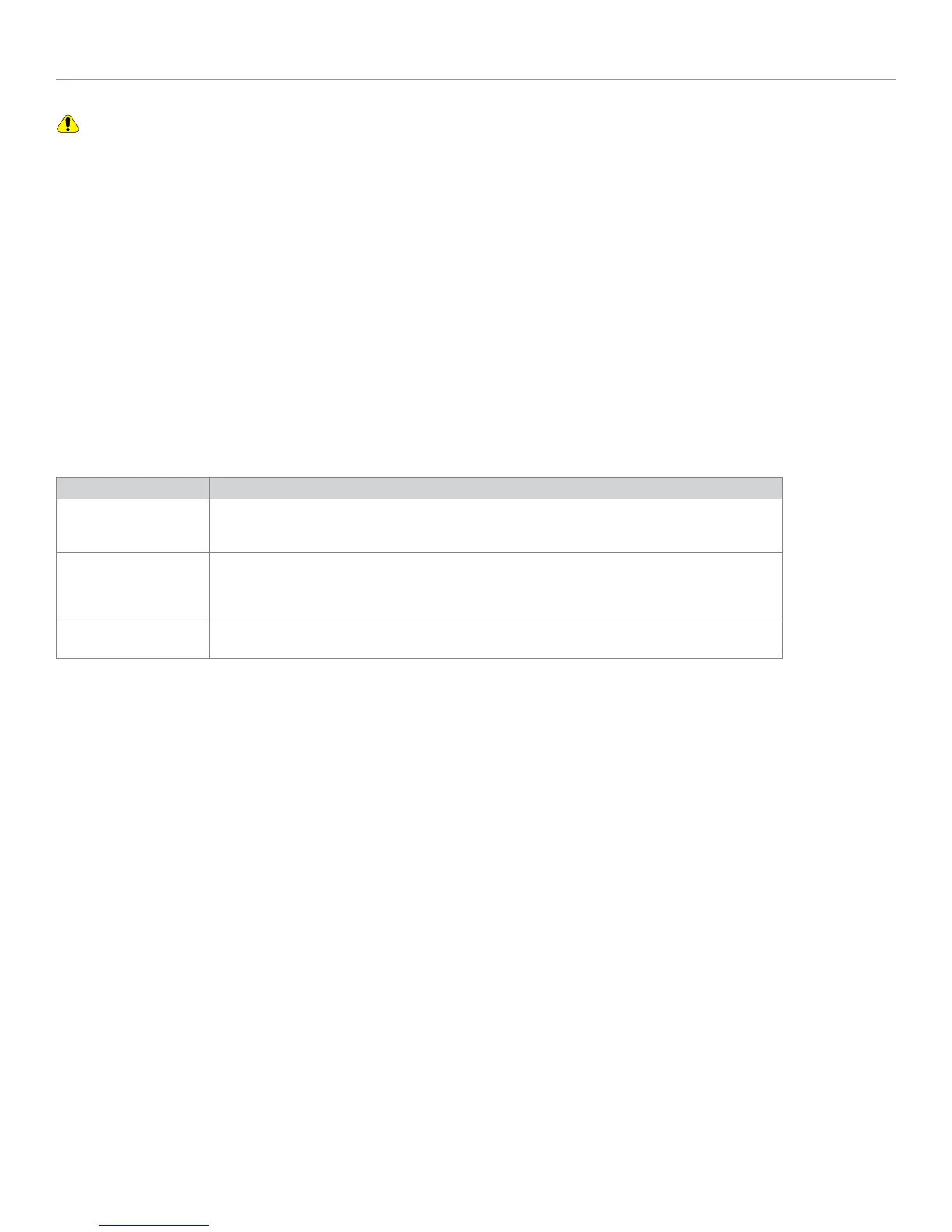
Additional connections required for vehicles equipped with a manual transmission (if not supported by firmware)
Connection Description
(-) E-Brake Status Input
(Black/White, pin 17)
Must be connected to a working emergency brake in the vehicle. Although most vehicles have simple
(-) trigger emergency brake circuits note some vehicles do not and may require unique integration
methodologies.
(-) Door Trigger Input
(Green, pin 20) OR
(+) Door Input (Violet, pin
13)
Must be connected to a working door trigger in the vehicle, which monitors all doors. The unit must monitor
the door pins to allow the Ready Mode process to be enabled.
Note: Some vehicles may require unique integration methodologies for this circuit.
(AC) Tachometer Input
(Violet/White, pin 22)
Must be connected to a working tachometer signal in the vehicle (fuel injector, ignition coil, true tach, etc.)
and learned successfully to the DS4+.
Note: Refer to www.directechs.com for more information.
RF Systems
An RF System consists of one or multiple remotes, a Control Center (antenna), and an antenna cable – various combinations exist.
An RF System allows the vehicle owner to control the system with enhanced range. Two-way models are available. Please follow
the instructions included with the kit for appropriate installation and programming information.
8504D Combo Sensor
The 8504D Combo Sensor must be paired to the device before it can be used. To enter pairing, turn the vehicle ignition to the
ON position, then press and hold the programming button on the Control Center (antenna) until the LED starts flashing. Once
pairing mode has been entered, your Combo Sensor is ready to use.
Your Combo Sensor is preset for the majority of applications, however it can be adjusted using the DirectLink application, as well
as a compatible LED or LCD remote. Please refer to the instructions included with your sensor for more information on how to make
adjustments.