16
DS4+ VW10
© 2017-11-02 Directed. All rights reserved.
Type 4
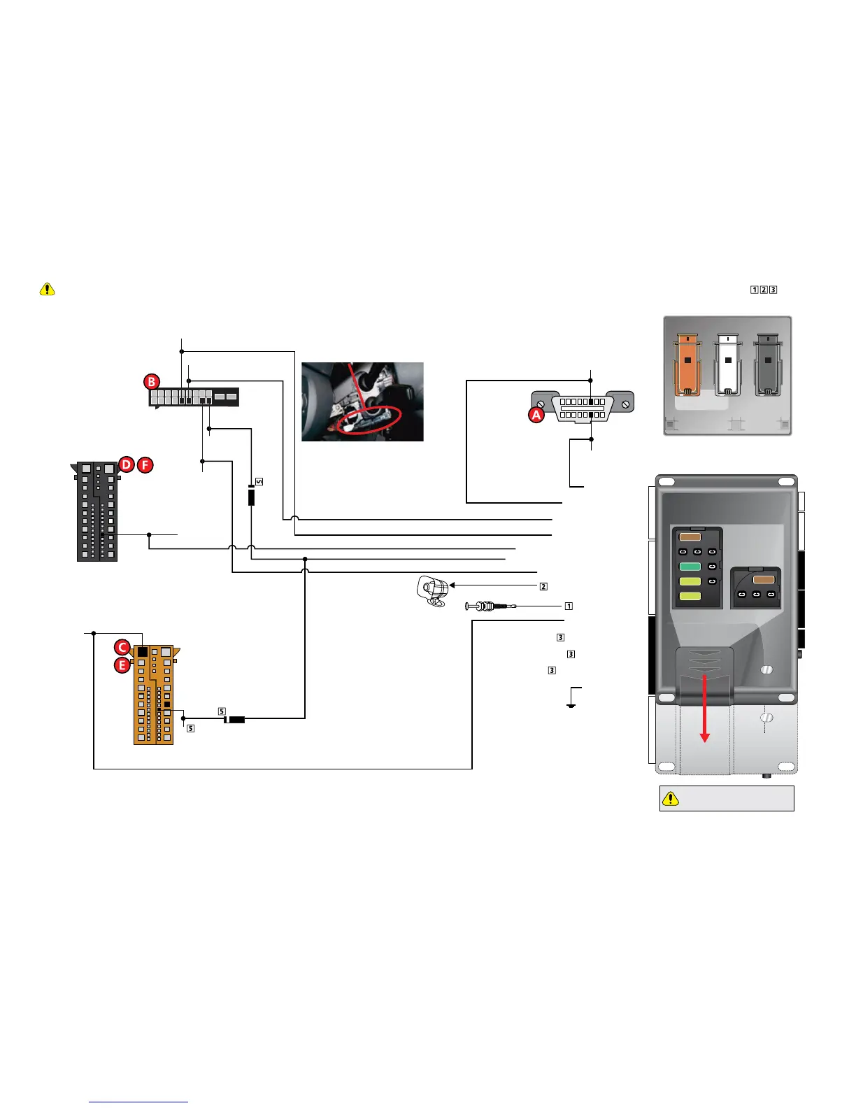
Refer to "Pre-installation and application warnings" on page 4 for important information, such as the description of special notes referenced in the diagram ( ).
16
8
9
1
Siren
Hood Pin
HS CAN High: Orange/Black, pin 6
HS CAN Low: Orange/Brown, pin 14
Steering Column Control Unit
12
29
28
42 25 1
52 41 24 11
FT CAN Low:
Orange/Brown, pin 15
(+) Ignition: Pin 17
(+) Starter: Red/Black
or Black/Gray,pin 18
FT CAN High: Orange/Green, pin 14
Brown VESCM connector C
(+) Brake: Black/Red, pin 17
(+)12V: Red/Blue or Red/Violet, pin 42
Steering Column Module
(behind steering
column trim)
17
10
1
20
[5] Diode 1A
[5] Diode 1A
Key Wrap: Lt. Green: 8
Key Wrap: Lt. Green/White: 9
(-) Ground: Black: 10
HS CAN Low: Tan : 1
(+) Starter / Brake Activation Output: White: 7
(-) Parking Lights Output: Lt.Green/Black: 1
(+) Ignition Output: Violet/Black: 8
HS CAN High: Tan/Black: 2
FT CAN High: Orange/Green: 4
FT CAN Low: Orange/Brown: 3
(+) 12V Input: Red: 6 & 12
Key Wrap: Lt.Green/Red: 7
(-) Hood Input: Gray: 21
(+) Siren Output: Brown/Red: 11
B
C
A
VESCM - Driver side under dashboard
Diagnostic
Connector
OBDII
DS4+
DS4
Slide
to open
Proper Fuse
Positioning
DS4+ DS4
It is important to check that the
fuses are positioned correctly.
MAIN (5A) (+)
(-) RLY3 PK LIGHT (15A) (+)
(-) ACC & START (30A) (+)
(-) FLEX RLY (20A) (+)
IGN (20A) (+)
MAIN (5A) (+)