17
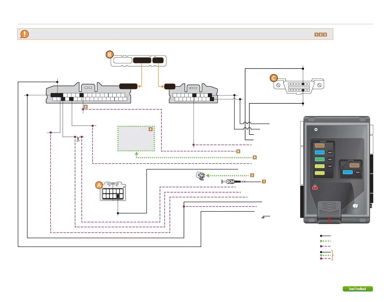
933.HONDA9 2.10.198.12 2022 Honda HR-V (Smart Key)
©2023 Directed. All rights
Refer to "Pre-installation and application warnings" for important information, such as the description of each special note referenced in the diagram ( ).
Wiring diagram without Vehicle Takeover
Siren
Hood Pin
(-) Hood Input: Gray: 21
(+) Siren Output: Brown/Red: 11
Immobilizer Data: Yellow/Black: 8
(-) Parking Lights Output: Lt. Blue/Black: 10
(+) 12V Input : Red: 6 & 12
(-) Ground: Black: 10
(+) Starter Output: Violet/Black: 8
(+) Ignition Output: Lt. Green: 8
(+) 12V Input: Lt. Green/Red: 7
10
20
1
11
2
12
3
13
4
14
56
15161718
789
19
Immo. Data:
Blue, pin 5
B-CAN
Low: Blue,
pin 11
B-CAN
High: Pink,
pin 1
12
20 19
3
21
4
22
56
24 23
78
26 25
9
27
10
2829
11
12
30
13
31
14
32
15
33
16
34
17
35
18
36
(+) Ignition: Pink, pin 17
(+) 12V:
Red, pin 18
(-) PTS: Lt. Blue, pin 11
(+) Starter: Green, pin 32
(+) Accessory 1:
Gray, Pin 16
Ignition Interrupt (vehicle side): Blue/White: 1
Ignition Interrupt (connector side): Blue: 3
(+) Accessory 1 Output: White: 5 & 11
Ignition Interrupt:
White, pin 34
Keyless Access Control Unit
(gray connector)
Keyless Access Control Unit
(gray connector)
Cut
Refer to the
Optional starter
disable connection
section for relay and
connection details.
HS CAN Low 2: Tan: 1
HS CAN High 2: Tan/Black: 2
HS CAN High 1: Orange/Green: 4
HS CAN Low 1: Orange/Brown: 3
Security Only
Mandatory Connections
Remote Start Only
Legend:
Remote Start + Security
22 812
4 2442
Slide to open
A module can also be used for
this installation.
IMPORTANT:
Position the
fuses correctly!
MAIN (5A) (+)
(-) RLY3 PK LIGHT (15A) (+)
(-) ACC & START (30A) (+)
(-) FLEX RLY (20A) (+)
IGN (20A) (+)
MAIN (5A) (+)
(-) RLY3/PK LIGHT (15A) (+)
5
5
30
20
20
15
15
(-) Parking Lights:
Gray, pin 8
Headlight Switch
(white connector)
123456
711
8
91012
DIAG-CAN High:
Gray, pin 6
DIAG-CAN Low:
Lt. Blue, pin 14
OBDII
Diagnostic
Connector
16
8
9
1
(-) GWA Output: Red/White: 4
(-) Push-to-Start Output: Lt. Green/Black: 1
1
1
2
2
Keyless Acces Control Unit
(behind instrument cluster)