24
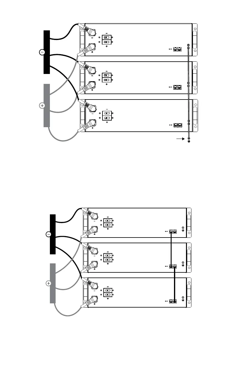
chassis ground
Figure 7. Battery Module Grounding
8. Connect all positive (+) cable lugs to the positive (+) busbar.
9. Connect all negative (-) cable lugs to the negative (-) busbar.
10. Connect all positive (+) battery module connectors to the positive (+) battery
module receiving pins and engage mating locks. Refer to Section 9.5, Terminal
Connections and Hardware.
11. Connect all negative (-) battery module connectors to the negative (-) battery
module receiving pins and engage mating locks.
Figure 8. Battery Busbar connection
12. Network the communication port of each battery module using a CAT5 cable.
13. If using the LYNK II Communication Gateway, connect it to the battery modules.
Attach a CAT5 cable to the LYNK port on the battery module. Attach the other