25
end of the cable to the LYNK Gateway.
Refer to Section 9.8.2, Network Installation, for instructions.
14. Set all battery module BMS to the ON position.
15. Energize the system by setting all battery module breakers to ON.
16. Close the circuit disconnect (if open).
NOTICE
Failure to securely engage the mating lock will increase resistance and lower voltage,
leading to burnout of the terminals and voiding of the warranty.
NOTE
• Whenever replacing an old battery module in a parallel string, use a battery module
of the same age, model, capacity, and voltage.
• Before installing the battery module in parallel, charge each module to 100% SOC.
9.8 LYNK Network
9.8.1 Network Layout
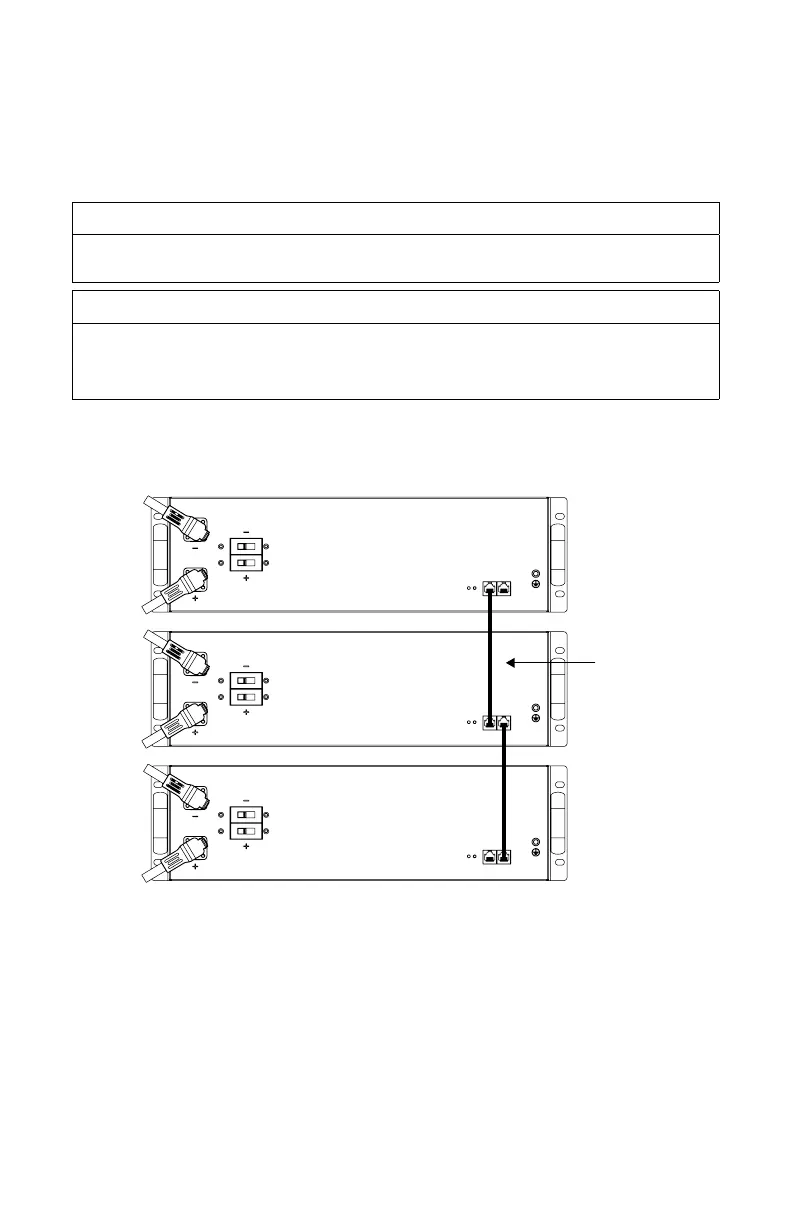
CAT 5
Figure 9. Battery modules connected through CAT5 network cable (provided)
9.8.2 Network Installation
Networking Guidelines:
• Separate data and power cables. Allow for separation between data and power
cables. Avoid data interference caused by running network cables bundled with
power cables.
• Allow for LYNK Network cable slack. Ensure that LYNK Network cables are slack
and not in tension.
• Isolate the LYNK Network. Do not mix other networks with the LYNK Network.