11 / 22
A separate transformer rated at 60 VA minimum must be used for each ECY-PS24 power supply for it to operate at full capacity. Choose a transformer
that can supply both the needs of the ECY-PS24 power supply (60VA) and any other 24VAC loads such as connected sensors and actuators: add up the
maximum power consumption of all 24VAC loads and multiply this sum by 1.3. If the resulting total (60VA plus 1.3 × 24VAC loads) is higher than 100VA,
use multiple transformers.
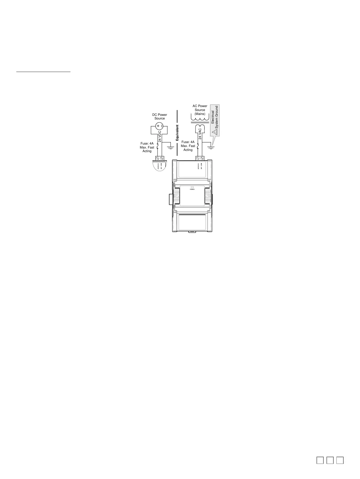
Use an external fuse on the 24VAC side (secondary side) of the transformer, as shown in the figure below, to protect all modules against power line
spikes and mis-wiring.
Each ECY-PS24 power supply can supply a maximum of 30W to loads connected to the right of it, up to the next connected power supply. See the
ECLYPSE Selection Tool to calculate the number of Input/Output Extension Modules that can operate with each power supply, the number of power sup-
plies required, and their location. The total power consumption of all modules including external 18VDC loads (such as 0 to 20mA current loop inputs)
must be 30W or less.
Maintain consistent polarity when connecting controllers and devices to the transformer. One terminal on the secondary side of the transformer must be
connected to the building’s ground. Ensure that the 24V COM terminals of all power supplies are connected to the grounded transformer secondary con-
nection.
24 VAC
AC Power
Source
(Mains)
Fuse: 4A
Max. Fast
Acting
Electrical
System Ground
Equivalent
24 VDC
Fuse: 4A
Max. Fast
Acting
+
–
DC Power
Source
Figure21: ECY-PS24 Power wiring