10 / 22
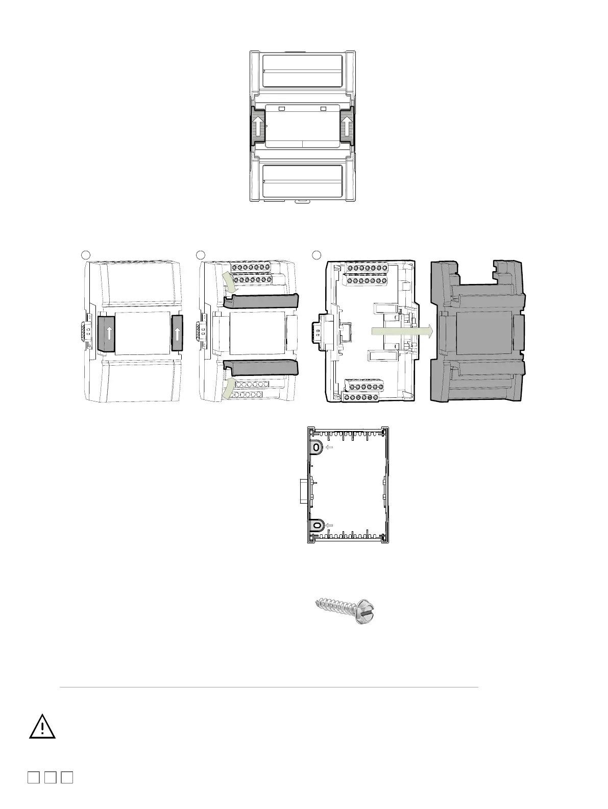
Figure17: Latches to Unlock a Module’s Front Assembly (ECY-S1000, left; ECY IO Module, right)
ð
For ECY IO modules
: Separate the front and back base by opening and pulling the hinged gull-wing covers, thereby separating the electrical
connectors between the two halves.
Figure18: ECY IO Modules have Gull-wing Front Assembly
2. Once the front assembly has been removed, use the back plate’s mounting holes to mark the location of any holes that need to be drilled.
Figure19: Typical Mounting Holes
3. Use the mounting holes to mark the location of any holes that need to be drilled.
4. Drill the holes.
5. Clean the surface
6. Mount the module using a No. 8 slotted hex, size: 1/4" or equivalent mounting hardware appropriate to the wall material type.
Figure20: Appropriate Mounting Hardware (Field Supplied)
7. To lock a module’s front assembly in place, attach the front assembly to the module’s back base by closing any gull-wing front assemblies (if applica-
ble) and pushing the two latches down.
Power Wiring with the ECY-PS24
Voltage
: 24VAC/DC; ± 15%, Class 2
For terminal block connector wiring best practices, see General Wiring Recommendations.
This is a Class 2 Product. Use a Class 2 transformer only (rated between 60 and 100VA at 24VAC) for each
ECY‑PS24 power supply.