9 / 22
HD15 cable
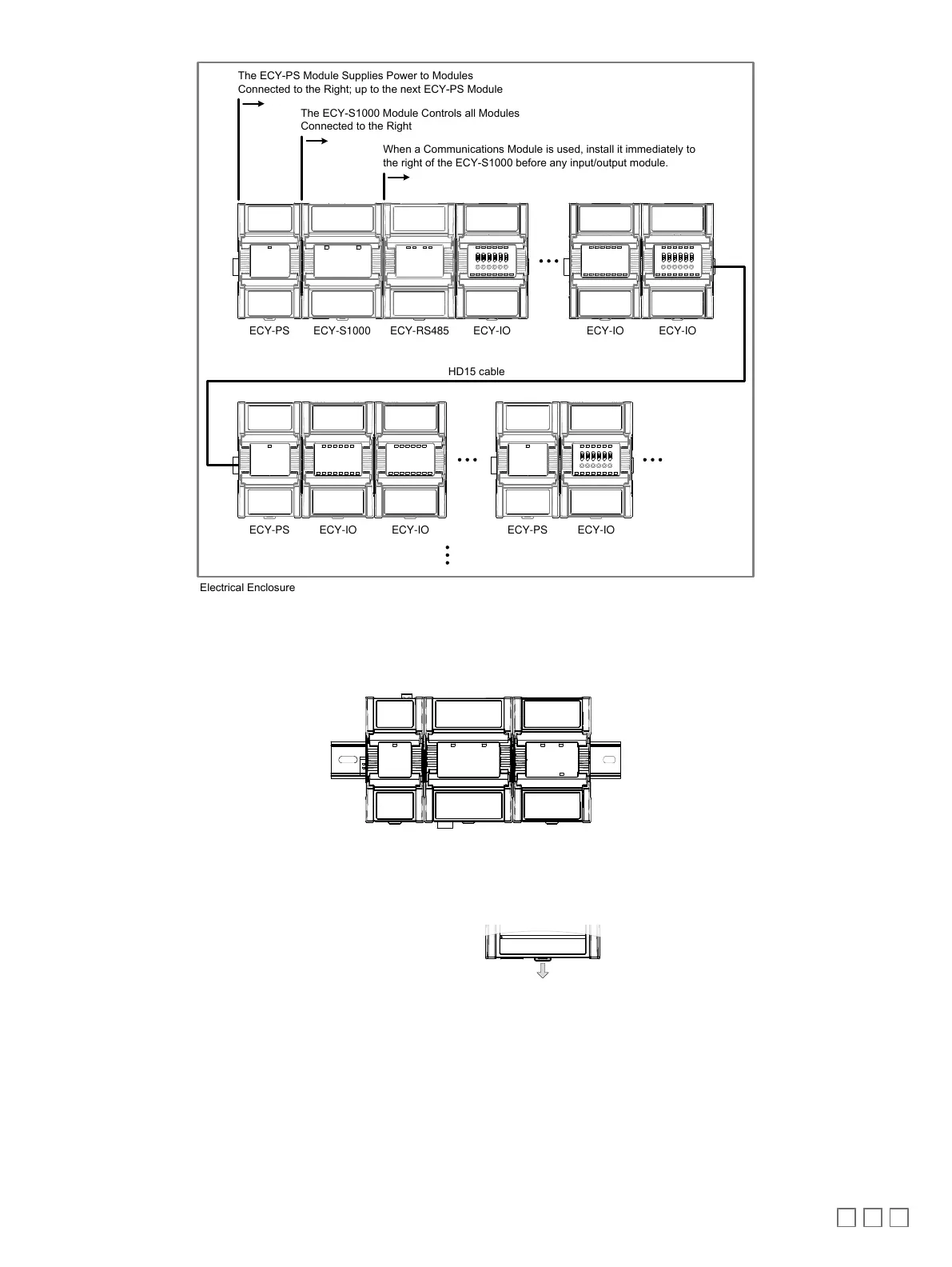
The ECY-PS Module Supplies Power to Modules
Connected to the Right; up to the next ECY-PS Module
The ECY-S1000 Module Controls all Modules
Connected to the Right
Electrical Enclosure
ECY-PS ECY-S1000 ECY-IO ECY-IO ECY-IO
ECY-PS ECY-IOECY-IOECY-IO
ECY-RS485
When a Communications Module is used, install it immediately to
the right of the ECY-S1000 before any input/output module.
ECY-PS
Figure14: Assembly Order
DIN Rail-Mounted Installation
1. Securely mount the DIN rail horizontally on the wall.
2. Clip the modules onto the DIN rail in the assembly order.
Figure15: DIN rail-mounted controller
3. Slide the modules together so that the side connectors of each module are firmly mated with the adjoining module. Use DIN rail clips to keep the row
of modules well secured together and to prevent the movement of any module along the DIN rail. Certain modules come with DIN rail clips in the box.
4. To detach the module from the DIN rail, separate the module from any other module located on either side. Use a flat screw driver to pull down on the
release clip located at the bottom center of the module and pull it off the DIN rail, bottom first.
Figure16: Typical DIN Rail-Mounting Release Clip
Wall-Mounted Installation
Modules should be mounted on a wall one module at a time. The first module of the assembly to be mounted should be the one to the very left (usually
an ECY Power Supply). Once this module has been attached to the wall, connect the next module on the right so that the side connectors are firmly cou-
pled and the modules are aligned straight. Now attach this module to the wall. Repeat until all modules are mounted in a row.
1. Before mounting a module, separate the front assembly from the back plate of each module to be mounted: push the two latches up to unlock a mod-
ule’s front assembly as shown below.
ð
For non-ECY IO modules
: Separate the front and back base by gently pulling the front assembly off of the back base, thereby separating the
electrical connectors between the two halves.