18
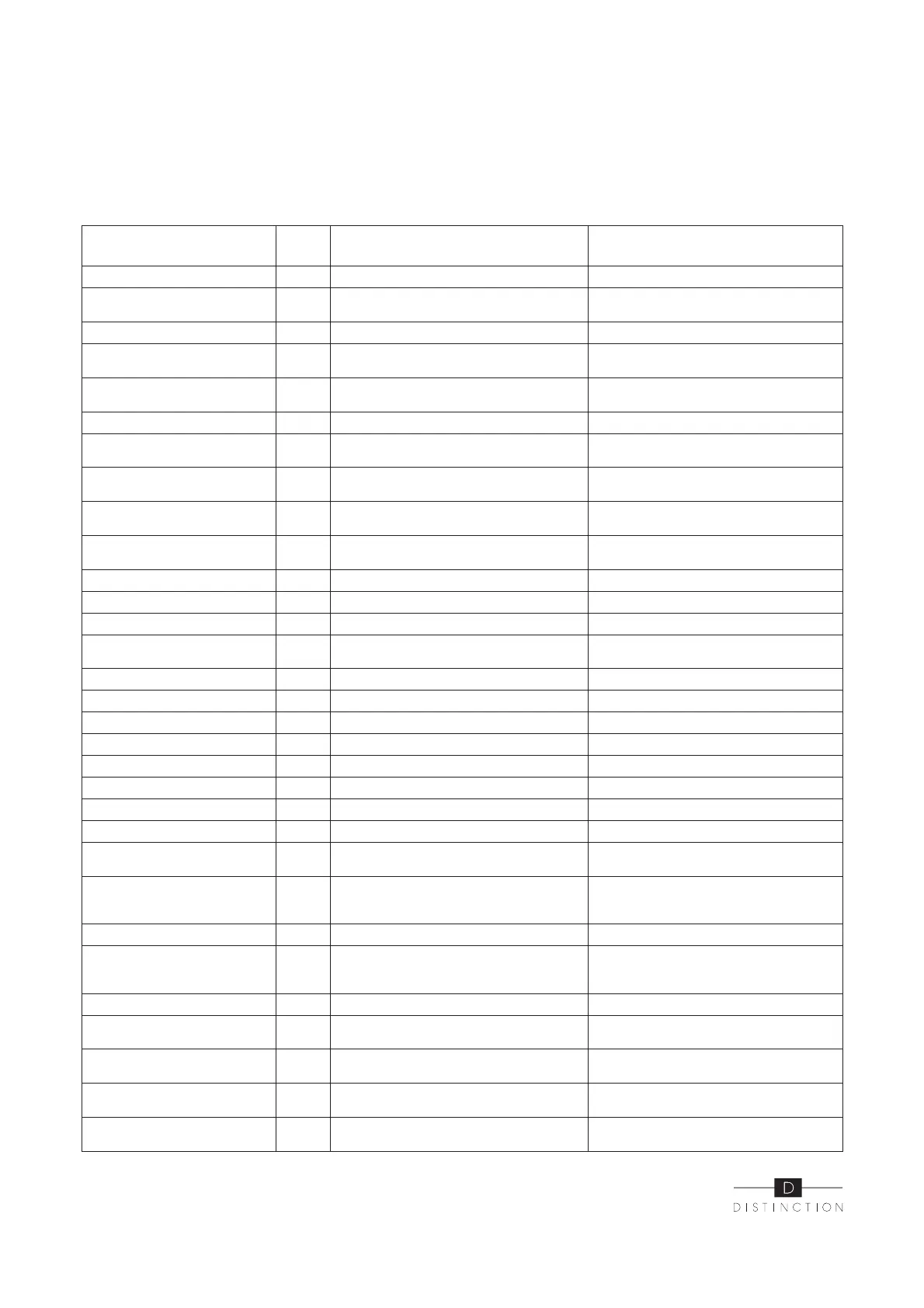
Frequency conversion board fault table :
Protect/fault
Fault
display
Reason Elimination methods
Drv1 MOP alarm F01 MOP drive alarm Recovery after the 150s
F02
Frequency conversion board and main
board communication failure
Check the communication connection
IPM protection F03 IPM modular protection Recovery after the 150s
Comp. driver failure F04 Lack of phase, step or drive hardware damage
Check the measuring voltage check
frequency conversion board hardware
DC fan fault F05
Motor current feedback open circuit or short
circuit
Check whether current return wires
connected motor
IPM overcurrent F06 IPM Input current is large Check and adjust the current measurement
Inverter DC overvoltage F07
DC bus voltage > Dc bus over-voltage protec-
tion value
Check the in put voltage measurement
Inverter DC lessvoltage F08
DC bus voltage < Dc bus over-voltage protection
value
Check the input voltage measurement
Inverter input lessvolt. F09
The input voltage is low, causing the inputcur-
rent is high
Check the input voltage measurement
Inverter input Overvolt. F10
The input voltage is too high, more than outage
protection current RMS
Check the input voltage measurement
Inverter sampling Volt. F11 The input voltage sampling fault Check and adjust the current measurement
Comm. error DSP-PFC F12 DSP and PFC connect fault Check the communication connection
Input over cur. F26 The equipment load is too large
PFC fault F27 The PFC circuit protection
Check the PFC swit ch tube short circuit
or not
IPM over heating F15 The IPM module is overheat Check and adjust the current measurement
Weak magnetic warn F16 Compressor magnetic force is not enough
Inverter input out phase F17 The input voltage lost phase Check and measure the voltage adjustment
IPM sampling cur. F18 IPM sampling electricity is fault Check and adjust the current measurement
V temp. Probe Fail F19 Sensor is short circuit or open circuit Inspect and replace the sensor
Inverter overheating F20 The transducer is overheat Check and adjust the current measurement
Inverter overheating Warn F22 Transducer temperature is too high Check and adjust the current measurement
Comp. over cur. warn F23 Compressor electricity is large The compressor over-current protection
Pressure sensor fault PP The pressure sensor is broken
Check or change the pressure sensor or
pressure
Fan Motor1 fault F031
1. Motor is in locked-rotor state
2.The wire connection between DC-fan motor
module and fan motor is in bad contact
1.Change a new fan motor
2.Check the wire connection and make sure
they are in good contact
Low AT Protection TP Ambient temp is too low
Fan motor2 fault F032
1. Motor is in locked-rotor state
2.The wire connection between DC-fan motor
module and fan motor is in bad contact.
1.Change a new fan motor
2.Check the wire connection and make sure
they are in good contact
Communication fault Speed control module and main
Communication fault (speed
control module)
E081
Speed control module and main board commu-
nication fail.
Check the communication connection.
Input over cur. warn F24 Input current is too large Check and adjust the current measurement
EEPROM error warn F25 MCU error
Check whether the chip is damaged Replace
the chip
V15V over/undervoltage fault F28 The V15V is overload or undervoltage
Check the V15V input voltage in range
13.5v~16.5v or not