Prepare - 54 JT520 Operator’s Manual
Plan Bore Path
CMW
Minimum Depth
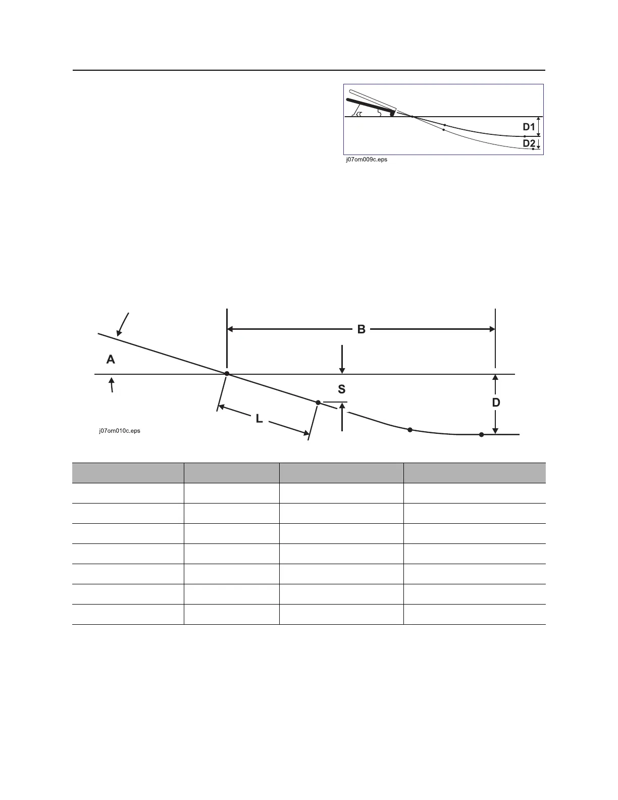
Because you must bend pipe gradually, entry pitch and
bend limits determine how deep the pipe will be when
it becomes horizontal. This is called the minimum
depth.
• To reduce minimum depth (D1), reduce entry
pitch. This also decreases setback.
• To increase minimum depth (D2), increase entry
pitch. This also increases setback.
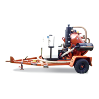
Bore Path Calculator
Entry pitch, setback, and minimum depth work together with bend limits to determine the bore path. To find
the setback (B) and entry pitch (A) that will take you to the desired minimum depth (D), use the chart
below.
Minimum depth (D) Entry pitch (A) Setback (B) Depth to begin steering (S)
2’ 0" (0.6 m) -18% 17’ 4" (5.3 m) 0’ 11" (0.28 m)
2’ 4" (0.7 m) -20% 18’ 8" (5.7 m) 1’ 0" (0.30 m)
2’ 9" (0.8 m) -22% 19’ 11" (6.1 m) 1’ 1" (0.33 m)
3’ 1" (0.9 m) -24% 21’ 2" (6.5 m) 1’ 2" (0.36 m)
3’ 6" (1.1 m) -26 22’ 5" (6.8 m) 1’ 3" (0.38 m)
3’ 11" (1.2 m) -28 23’ 8" (7.2 m) 1’ 4" (0.41 m)
4’ 5" (1.4 m) -30 24’ 11" (7.6 m) 1’ 5" (0.43 m)
IMPORTANT: Numbers in table based on 70’ (21.3 m) minimum bend radius, beacon housing, EZ-
Connect, connector, transition sub, and 1/3 of first drill pipe (L, totaling 5’ [1.5 m]) in the ground before
steering.