Before connecting the power supply, make sure the plate data correspond to that of the
mains power supply.
An omnipolar disconnection switch with minimum contact gaps of 3 mm must be included in
the mains supply.
Check that upstream of the electrical installation there is an adequate residual current circuit
breaker and a suitable overcurrent cutout.
Use a H05RN-F 3G1,5 or H05RR-F 3G1,5 type electric cable and connect to the terminals L
(brown), N (blue) in the automation.
Connect the yellow-green earth wire to the appropriate terminal already connected to the motor.
Secure the cable using the special cable clamp and remove the outer sheath near the terminal
only.
Connection to the mains power supply, in the section outside the automation, is made with
independent channels and separated from the connections to the control and safety devices.
The channel must go into the automation through the holes on the base plate.
Make sure there are no sharp edges that may damage the power supply cable.
Make sure that the mains power supply (230 V) conductors and the accessory power supply
(24 V) conductors are separate.
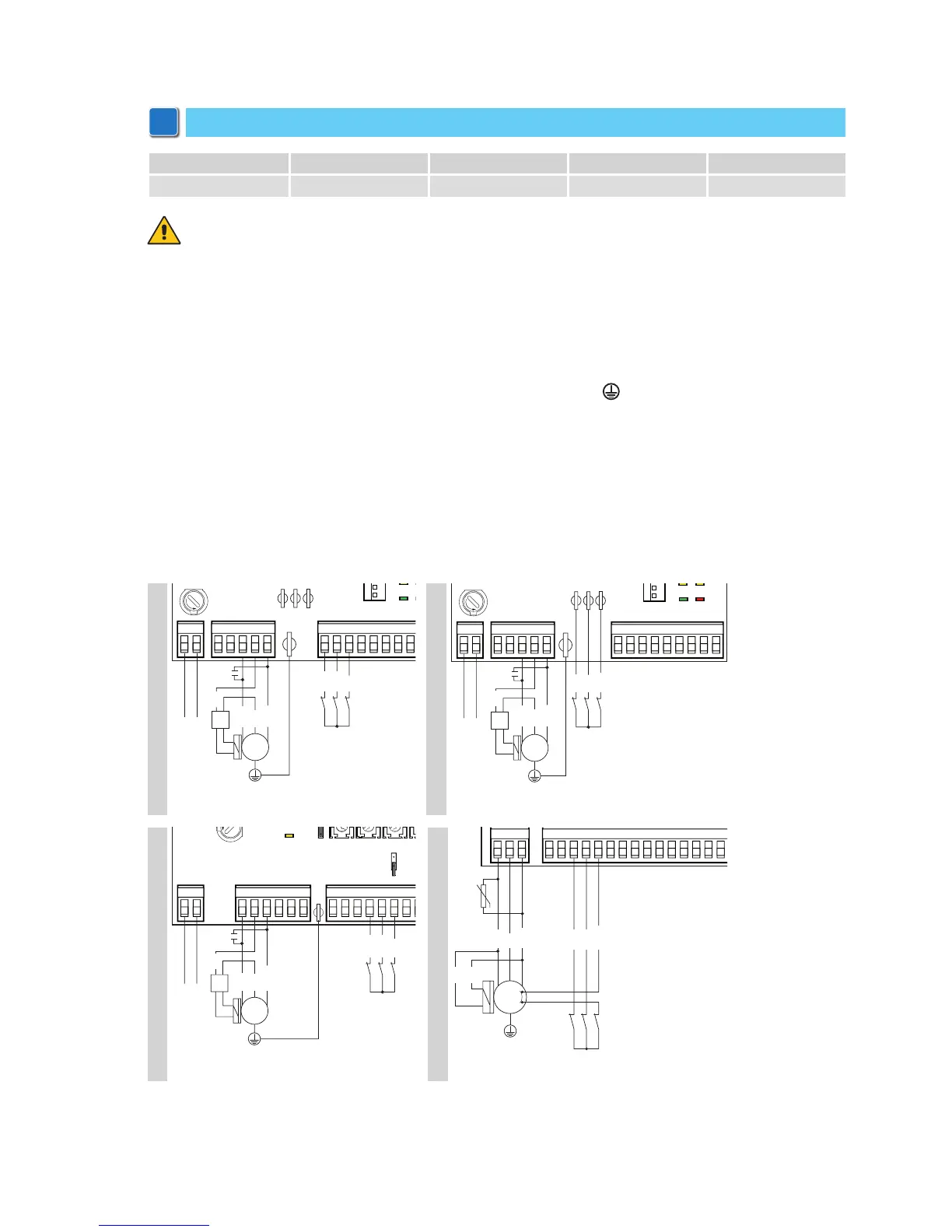
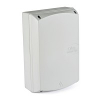
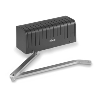
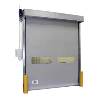
8. Electrical connections
CROSS18 CROSS18E CROSS18VE CROSS19V
Control panel E1A - LOGICM E1A LOGIC M E1T
NOTE: the electrical connections and starting of the gearmotor are illustrated in the control panel in-
stallation manual.