LUXEPaINTBaLL.COm
866.573.LUXE(5893)
5
6
7
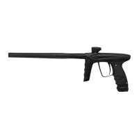
STEP FOUr PrESSUrE CONTrOL PISTON
THE BRASS PRESSURE CONTROL PISTON and regulator spring may come out with the lower regulator
housing. If they do, the pressure control piston may be pulled out of the lower regulator housing by hand.
If the pressure control piston remains in the regulator housing, the regulator spring can be dropped out by
tilting the upper regulator housing, and a 5/16-inch allen wrench may be used to push the pressure control
piston out from the top.
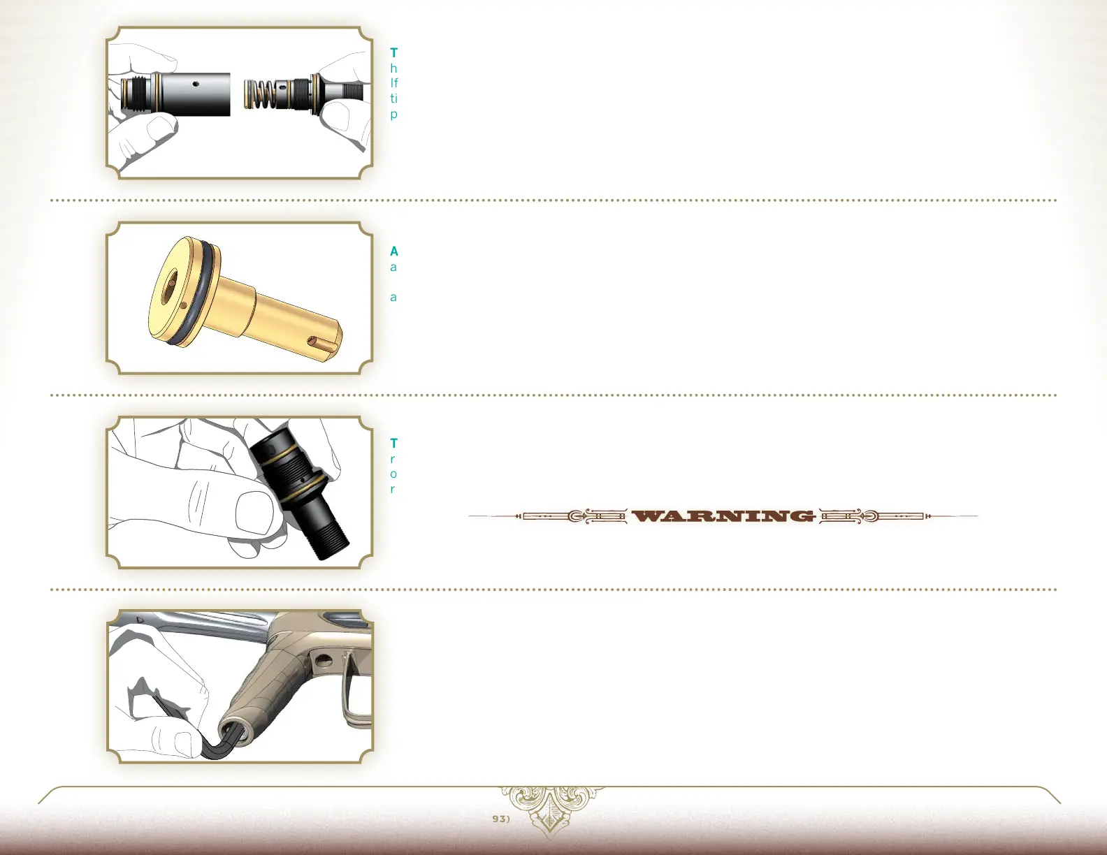
STEP FIVE INSPECT SEaLS aND rEGULaTOr HOUSING
AT THIS LEVEL OF DISASSEMBLY, the pressure control piston seal and regulator housings may be inspected,
and cleaned with a soft cloth or cotton swab. If the piston seal shows signs of excessive wear or damage, it
must be replaced. Lightly lubricate all o-rings with GR33SE™ for reassembly. For normal maintenance this is
all that must be done.
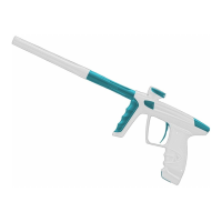
STEP SIX VELOCITY aDJUSTEr
THE VELOCITY ADJUSTER SHOULD only be removed if leaking. Using a narrow pair of snap-ring pliers,
remove its lock ring, then unscrew it clockwise (the velocity adjuster is left-hand threaded) out the bottom
of the lower regulator housing. Clean, inspect, lubricate and if necessary replace the adjuster's o-rings, then
reinstall it with the reverse procedure.
PARTS OF THE LUXE® INTEGRATED AIR VERTICAL REGULATOR USE LEFT-HANDED THREADS. THESE PARTS MUST
BE TURNED COUNTER-CLOCKWISE TO SCREW THEM IN AND CLOCKWISE TO UNSCREW THEM—THE OPPOSITE
DIRECTION OF NORMAL SCREWS.
STEP SEVEN rEaSSEmBLE rEGULaTOr
REASSEMBLY IS PERFORMED in the reverse order of disassembly. Insert the pressure control piston into the
upper regulator housing, followed by the regulator spring. Screw the lower regulator housing into the upper
housing. Look in the lock screw holes to make sure the two halves are aligned properly. Reinstall the lock
screws, securing them with blue Loctite® 242. When the housing halves are properly aligned, the lock screws
will be able to sit flush with the body. If they do not sit flush, remove them and realign the body halves. Do not
over-tighten the lock screws. Using a 5/16-inch allen wrench from the bottom, screw the regulator into the bi-
directional ASA then slide the regulator cover in place and secure it with the cover lock.
4
PaGE 31
6.2 SErVICING THE VErTICaL rEGULaTOr