LUXEPaINTBaLL.COm
866.573.LUXE(5893)
aDVaNCED maINTENaNCE 6.4 GrIP FramE rEmOVaL
REMOVING THE LUXE® GRIP FRAME IS NOT a part of regular maintenance. It should only need to be
performed if replacing the anti-chop Vision eyes or solenoid valve. It is recommended that this procedure
be performed by a Certified Luxe® Technician, as re-assembly errors may cause leaks in the Integrated Air
system or damage to the Luxe® body.
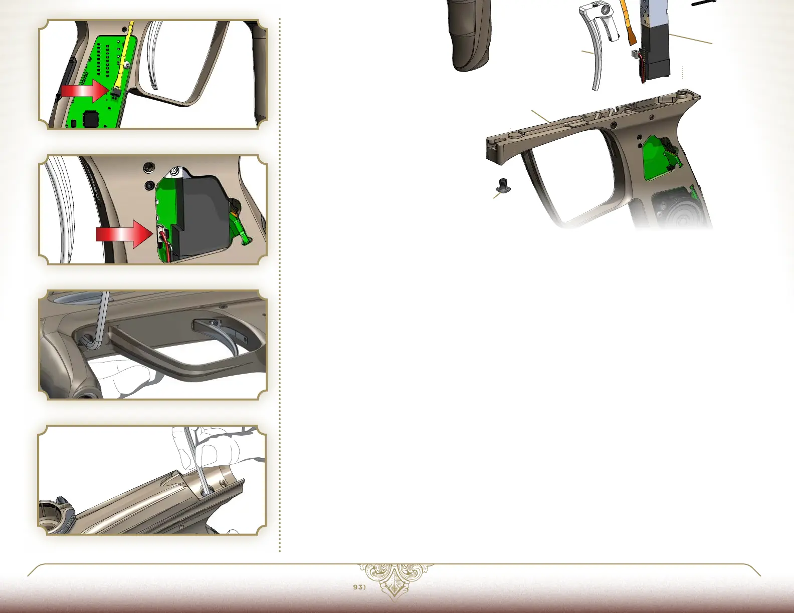
To remove the grip frame first unload and degas the Luxe®. Next use a 5/64-inch allen wrench to remove
all four grip screws and the flexible rubber grip. Unplug both the flexible Vision eye ribbon [FIG. 4] and the
solenoid valve [FIG. 5.]
Use a 1/8-inch allen wrench to loosen the forward grip frame screw [FIG. 6.] Use the same allen wrench to
loosen the rear grip frame screw from the top [FIG. 7.]
While carefully supporting both the Luxe® body and grip frame, completely remove the front and rear grip
frame screws. Next, carefully lift the receiver apart from the grip frame. Take care not to snag the solenoid
valve connector, and notice how the Vision eye cable is routed through slots in the bottom of the receiver.
With the receiver and grip frame apart, the solenoid valve and solenoid manifold may be removed from the
Luxe® receiver by removing their respective screws. A 1.5mm allen wrench will be required to remove the
screws holding the solenoid valve to its manifold. Once the solenoid manifold is separated from the receiv-
er, the Vision eye strip is free to be lifted out of its channel in the Luxe® body. With the ball detent assem-
blies removed (see MAINTENANCE 5.2) the eyes may be lifted out of their pockets and passed down through
their openings in the receiver.
Reassembly is performed in the reverse order of disassembly. It is critical to ensure that the solenoid valve
wires and Vision eye flex strip are routed properly, and do not become bent or pinched. The sensor and
emitter ends of the Vision eye flex strip are keyed with a notched corner to ensure that they are placed on
the correct side of the marker. When plugging the Vision flex strip into the Luxe® circuit board, be certain
the side with the shiny metal contact surfaces faces outward, away from the circuit board. The forward and
rear grip frame screws must be snug, but not overtightened. Over-tightening the solenoid valve or solenoid
manifold screws may cause permanent damage.
FIG. 4
FIG. 5
FIG. 6
FIG. 7
PaGE 33
6.3 BaLL DETENT aSSEmBLIES
maIN GrIP FramE COmPONENTS
GRIP FRAME SCREWS
VISION EYE STRIP
SOLENOID MANIFOLD
SOLE NOI D VA LV E
TRIGGER
GRIP FRAME
6
1
1
2
3
4
5
6
5
4