Digital Monitoring Products DualCom Programming and Installation Guide
8
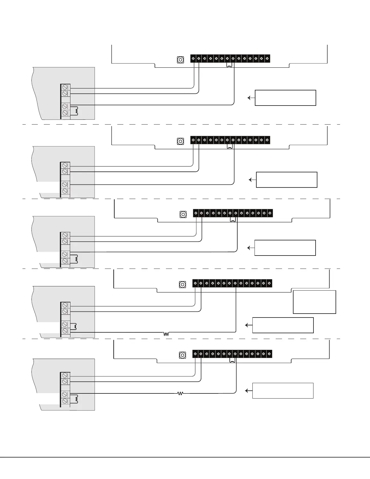
+DC- Z1 Z2 Z3 G +Z4- 01 02 T1 R1 T2 R2
+DC- Z1 Z2 Z3 G +Z4- 01 02 T1 R1 T2 R2
+DC- Z1 Z2 Z3 G +Z4- 01 02 T1 R1 T2 R2
+DC- Z1 Z2 Z3 G +Z4- 01 02 T1 R1 T2 R2
+DC- Z1 Z2 Z3 G +Z4- 01 02 T1 R1 T2 R2
+DC- Z1 Z2 Z3 G +Z4- 01 02 T1 R1 T2 R2
DMP Panel
12 VDC Aux. Output
+
-
ADEMCO Panel
+
-
NAPCO Panel
+
-
Z4 -
DSC Panel
+
-
10k ohm
1k
ohm for supervision
1k ohm
1k ohm
1k
ohm for supervision
2.2k
ohm for supervision
Program Zone 4
DO - Alarm
AO - Alarm
Voltages above 1.4 VDC
are considered Alarm
24 VDC Panel
1k ohm
1k ohm
+
-
4.7k
ohm for supervision if required
Use 18-22 AWG for
power supply
connection
12 VDC Aux. Output
12 VDC Aux. Output
12 VDC Aux. Output
12 VDC Aux. Output
Voltages below 0.7 VDC
are considered Alarm
Voltages above 1.4 VDC
are considered Alarm
Voltages above 1.4 VDC
are considered Alarm
Voltages above 1.4 VDC
are considered Alarm
Z4 -
Z4 +
Z4 -
Z4 +
Z4 -
Z4 +
1k ohm
Z4 -
Z4 +
24 VDC BELL +
BELL -
12/24 VDC BELL +
BELL -
12 VDC BELL +
BELL -
12 VDC BELL +
BELL -
Use 18-22 AWG for
power supply
connection
Use 18-22 AWG for
power supply
connection
Use 18-22 AWG for
power supply
connection
Use 18-22 AWG for
power supply
connection
Figure 8: Zone 4 Bell Connection