DualCom Programming and Installation Guide Digital Monitoring Products
1
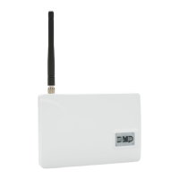
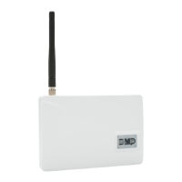
ABOUT THE COMMUNICATOR
The DualCom™ communicator provides a fully supervised alarm communication path and integrated primary and
secondary communication on one PCB. For commercial fire or residential fire installations, DualComNF modules
feature primary network communication, secondary cellular communication, and two sets of tip and ring terminals.
For non‑fire residential installations, DualComWZ modules feature built‑in primary Wi‑Fi communication, secondary
cellular communication, Z‑Wave integration, and one set of tip and ring terminals.
Use the DualCom communicator to take over panels. The communicator can be connected to a control panel’s dialer
output and used to capture Contact ID messages based on SIA DC‑05‑1999.09‑DCS.
The
c
ommunicator also provides four input zones and two open‑collector outputs for connection to control panel
outputs and zones. Connect to the bell output of an existing control panel using zone4 on the communicator. The
communicator operates in a variety of applications: CID Dialer Connection, Zones1‑4 Input Connections, or Zone4
Bell Connection. See Applications.
DualComNF modules include a red enclosure and a Model 685‑R (Red) Back Box.
Features
• Can be powered from 12VDC or 24VDC
• Zone1‑4 terminals with 12V and 24V power input
• EASYconnect™
• 2sets of tip and ring terminals (DualComNF only)
• 1set of tip and ring terminals (DualComWZ only)
• Programming header for connecting to a programming keypad
• LED to indicate armed state
What is Included
• PCB with enclosure
• Model685
‑
R Back Box (DualComNF only)
• Hardware pack
• External antenna
SYSTEM COMPONENTS
Terminals
Power Connection Terminals
The communicator may be powered from the 12VDC or 24VDC auxiliary output of the control panel. Observe
polarity and use 18‑22 AWG wire to connect the
communicator
terminal +12 to the +12 or +24V positive terminal
on the
control panel auxiliary output
. See Figure1. Connect the communicator terminal G(ground) to the negative
terminal on the control panel auxiliary output.
Control Panel Standby Power
During a power outage, the communicator draws power from the control panel’s backup battery. The communicator
must be included in the standby battery calculations for the control panel.
Zones 1‑4
Terminals Z1 to Z3, G(ground), Z4+ and Z4‑ provide four zones to connect to individual relay outputs on the control
panel. Zone4 (Z4+ and Z4‑) can be connected to the control panel bell output. See Zone4 Bell Connection.
Open‑Collector Outputs
Terminals O1 and O2 can be programmed to indicate the activity of the zones or conditions occurring on the system.
Open‑Collector outputs do not provide a voltage but instead switch‑to‑ground the voltage from another source.
Maximum voltage is 30VDC at 50mA. The outputs can respond to any of the conditions listed below:
• Activation by zone condition: Steady, Pulse, Momentary, or Follow
• Communication
• Armed area annunciation
• Remote Arming Output
Dialer Connection
Directly connect the Telco phone line (tip and ring) from the control panel to the terminalR(Ring) and one into
terminalT(Tip). See CID Dialer Connection.