Digital Monitoring Products DualCom Programming and Installation Guide
6
APPLICATIONS
The DualCom communicator can be used in a variety of applications.
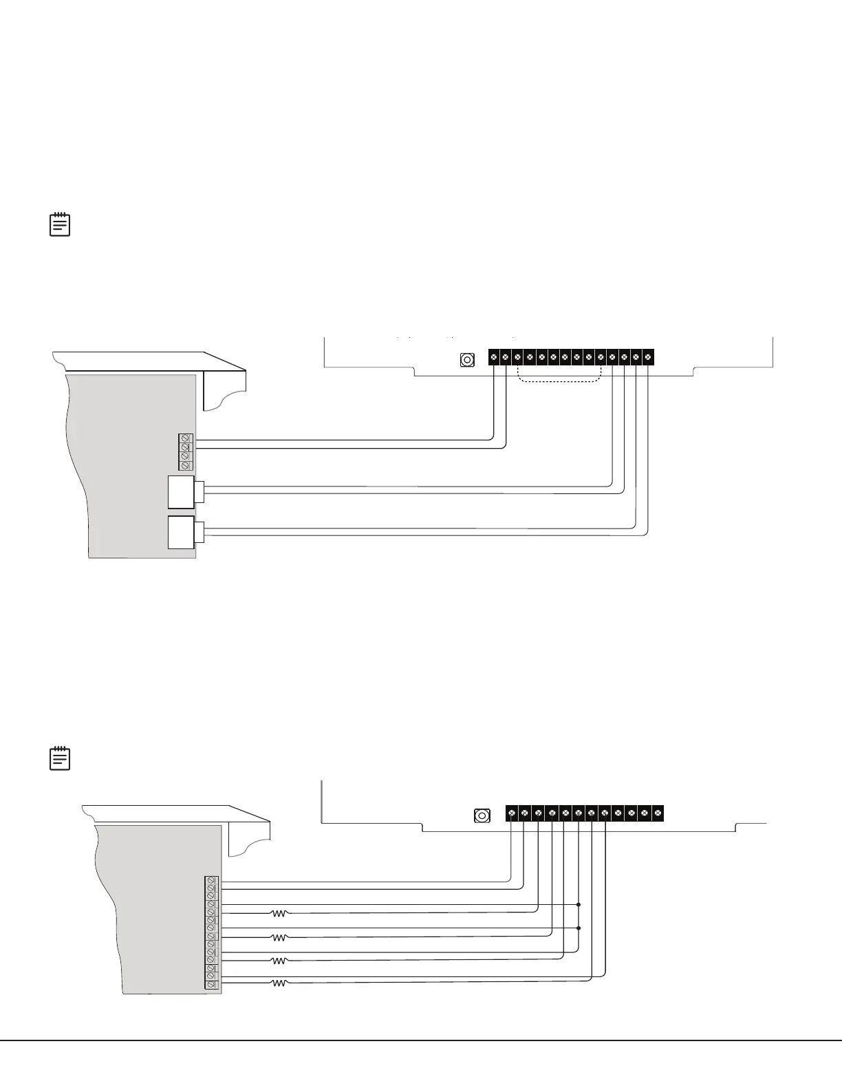
CID Dialer Connection
Directly connect one or both tip and ring terminals from the control panel to the communicator. See Figure4. This
connection captures Contact ID messages from any fire panel that are based on the SIA communication standard
DC‑05‑1999.09‑DCS. Messages are then formatted into a Serial3 message and sent to an SCS‑1R Receiver or
SCS‑VRReceiver.
Note: CID Dialer Connection cannot be used when using Zone 4 Bell Connection. Do not connect telephone
company wires to the communicator. Remove any connected telephone company wires from the control panel.
Communication Failure (DualComNF only)
The phone line voltage on the second tip and ring will drop when DualComNF is in a communication failure state. This
triggers the host panel to annunciate a communication failure. When communications have restored on DualComNF,
voltage will be restored on the second tip and ring terminal, allowing the host panel to see a restoral on the phone
line..
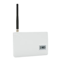
Zones 1‑4 Input Connection
Connect each control panel relay output to a zone on the communicator. For programming purposes, the zone
numbers are 1‑4. The following is an example of how you might use this application for a burglary or fire alarm.
Burglary (DualComWZ only)
Use a normally closed output on a burglary control panel to indicate a burglary alarm. The communicator zone should
be programmed with a zone name and burglary zone type. When the output on the control panel turns on and trips
the communicator zone, a message is sent to an SCS‑1R or SCS‑VR receiver at the central station. The zone name
programming can be used to describe which control panel zone indicated a burglary. See Figure5.
Note: Zone4 can only be used as a standard input zone when not programmed as zone type Auxiliary2 (A2). See
Zone4 Bell Connection.
Figure 4: Wiring Diagram for Tip and Ring Connection
+DC- Z1 Z2 Z3 G +Z4- 01 02 T1 R1 T2 R2
Use 18-22 AWG for
power supply connection
CONTROL PANEL TIP
CONTROL PANEL RING
12/24 VDC Aux. Output +
-
Ground
Control Panel
The panel or separate power
supply must be listed for fire,
regulated, and power limited.
Telephone
Jack
Connector
BELL -
BELL +
CONTROL PANEL TIP
CONTROL PANEL RING
Telephone
Jack
Connector
NC (No Connection)
Switch
(CellComDF Only) Connect the Ethernet within 20 ft and
routed in
conduit to network equipment in the same room
(supervised, power limited).
+ DC -, T1 R1, and T2 R2 shall be connected
within 20 ft in the same room and routed in
conduit.
PROG
ETHERNET
+DC- Z1 Z2 Z3 G +Z4- 01 02 T1 R1
Use 18-22 AWG for
Power Supply connection
Z3 +
Z4 +
Z4 -
GND
12 VDC Aux. Output
+
-
Ground
Burglary
Control Panel
The panel or separate power
supply must be 12 Volt Regulated
and Power Limited.
Z1 +
Z2 +
Normally Open
Common
Normally Closed
Normally Open
Common
Normally Closed
Normally Open
Common
Normally Closed
Normally Open
Common
Normally Closed
1k ohm
1k ohm
1k ohm
1k ohm
Figure 5: Wiring Diagram for Burglary Zones 1‑4