DualCom Programming and Installation Guide Digital Monitoring Products
7
Zone4 Bell Connection
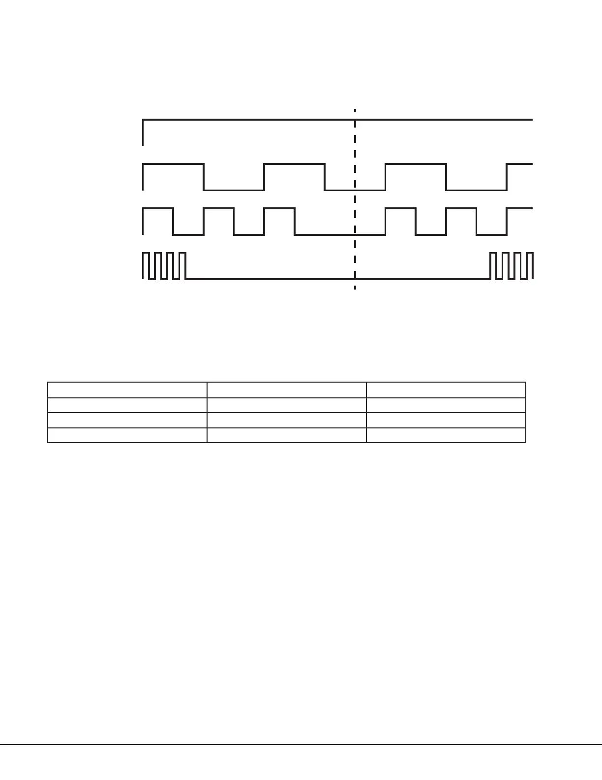
Zone4 (Z4+ and Z4‑) can be connected to the control panel bell output. This zone detects an alarm condition on the
control panel by monitoring the voltage and cadence timing of the bell output. The communicator evaluates the first
3.5seconds of bell cadence timing to detect the type of alarm sent. See Figure7.
To enable alarm detection operation, zone4 bell connection must be programmed as zone type (A2) in zone
information programming. See Table2 for bell cadence type, zone number, and type of message sent to the receiver.
The communicator generates zones5 and6 using the zone name of zone4 to send to the central station. Zones5
and6 cannot be preprogrammed in zone information. CID Dialer Connection cannot be used when using zone4 bell
connection. See Figure8.
Bell Cadence Zone Number Type of Message
Steady Zone4 Burglary
Pulse or Temporal3 Zone5 Fire
Temporal4 Zone6 Emergency or Carbon Monoxide
Figure 6: Wiring Diagram for Zones 1‑4
PROG
LOAD RESET
ETHERNET
+DC- Z1 Z2 Z3 G +Z4- 01 02 T1 R1 T2 R2
Use 18-22 AWG for
power supply connection
Z3 +
Z4 +
Z4 -
GND
12 VDC Aux. Output
+
-
Ground
Fire
Control Panel
The panel or separate power
supply must be 12 V regulated
and power limited.
Z1 +
Z2 +
Normally Open
Common
Normally Closed
Normally Open
Common
Normally Closed
Normally Open
Common
Normally Closed
Normally Open
Common
Normally Closed
1k ohm
1k ohm
1k ohm
1k ohm
Figure 7: Zone 4 Bell Cadence Information
Steady
Pulse
Temporal 3
Temporal 4
1.0 sec 1.0 sec 1.0 sec 1.0 sec 1.0 sec
.5 sec .5 sec .5 sec 1.5 sec .5 sec.5 sec .5 sec .5 sec
3.5 sec
Each .1 sec On
5.0 sec
On
O
On
O
On
O
On
O
Each .1 sec O
Each .1 sec On
Each .1 sec O
Table 2: Message Breakdown