Digital Monitoring Products DualCom Programming and Installation Guide
4
INSTALLATION
Select a Location
Install the communicator away from metal objects. Do not mount the communicator inside or on a control panel metal
enclosure. Mounting the communicator on or near metal surfaces impairs cellular performance.
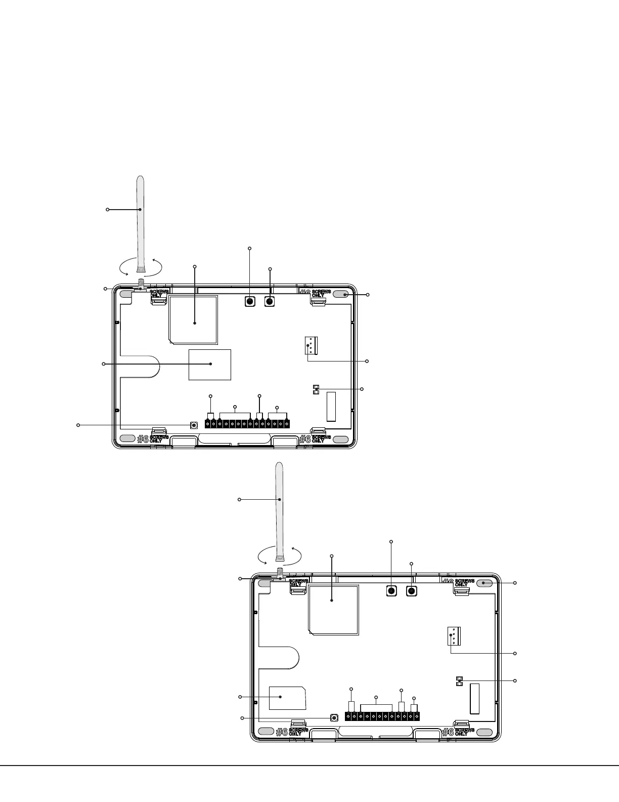
Mount the Communicator
The communicator should be mounted to a wall using the included #6 screws in the mounting holes. See Figure1a
and 1b. Mount the communicator in a secure, dry place to protect the communicator from damage due to tampering
or the elements. It is not necessary to remove the PCB when installing the communicator.
Cellular
Antenna
PROG
LOAD RESET
ETHERNET
S
N
+DC- Z1 Z2 Z3 G +Z4- 01 02 T1 R1 T2 R2
DC Power
Zones 1-4
Tip & Ring
Outputs
Cell
Modem
Load
Button
Reset
Button
Mounting
Hole
Programming
Connection
Backlit Logo,
Power/Armed
LEDs
SMA
Connector
Tamper
Network
Connection
Figure 1a: DualComNF System Components
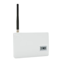
PROG
LOAD RESET
S
N
+DC- Z1 Z2 Z3 G +Z4- 01 02 T1 R1
Figure 1b: DualComWZ System Components
Tamper
SMA
Connector
Cellular
Antenna
Cell
Modem
Load
Button
Reset
Button
Mounting
Hole
Programming
Connection
Backlit Logo,
Power/Armed
LEDs
DC Power
Zones 1-4
Outputs
Tip & Ring
Wi-Fi