4
Remove the Cover
The keypad housing is made up of two parts: the cover, which
contains the circuit board and components, and the base. Use the
following steps and Figure 1 to separate the keypad cover and
base:
1. Insert a flat screwdriver into one of the slots on the bottom
of the keypad and gently lift the screwdriver handle toward
you while pulling the halves apart. Repeat with the other
slot.
2. Using your hands, gently separate the front from the base
and set the cover and components aside. See Figure 1.
Harness Wiring
Use 1k Ohm EOL resistors, DMP Model 311 on keypad zones 1-4.
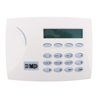
Models 7060/A, 7063/A, 7160, and 7163
Supplied with a 4-wire harness for panel keypad bus connection.
Models 7070/A, 7073/A, 7170, and 7173
Supplied with a 12-wire data bus/zone harness. Four wires connect to the keypad
bus. The remaining eight wires are for the four zone inputs, four wires for each
zone.
Models 7073/A and 7173
Supplied with one 5-wire output/reader harness.
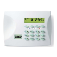
Keypad
Wall
Insert small screwdriver
and lift to remove cover.
Do not twist.
Figure 1:
Removing the Keypad Cover
Install the Keypad