ELECTRICAL CONTROLS
(1)
Band
drive
motor
functions
are
controlled
by
a
"pull-to-start
"
and
"push-to-stop"
pushbutton
on
electrical
enclosure.
CAUTION: Always disconnect power to machine
before opening electrical enclosure box.
(2)
The
electrical
enclosure
also
has
a
Coolant
"on
-
off
"
selector
switch
which
controls
coolant
pump
operation
.
SAW
GUIDE INSERT ADJUSTMENT
(1)
Turn
saw
guide
insert
adjustment
screw
until
inserts
touch.
Do not tighten.
(2)
Turn
screw
counterclockwise
1-1/2
turns.
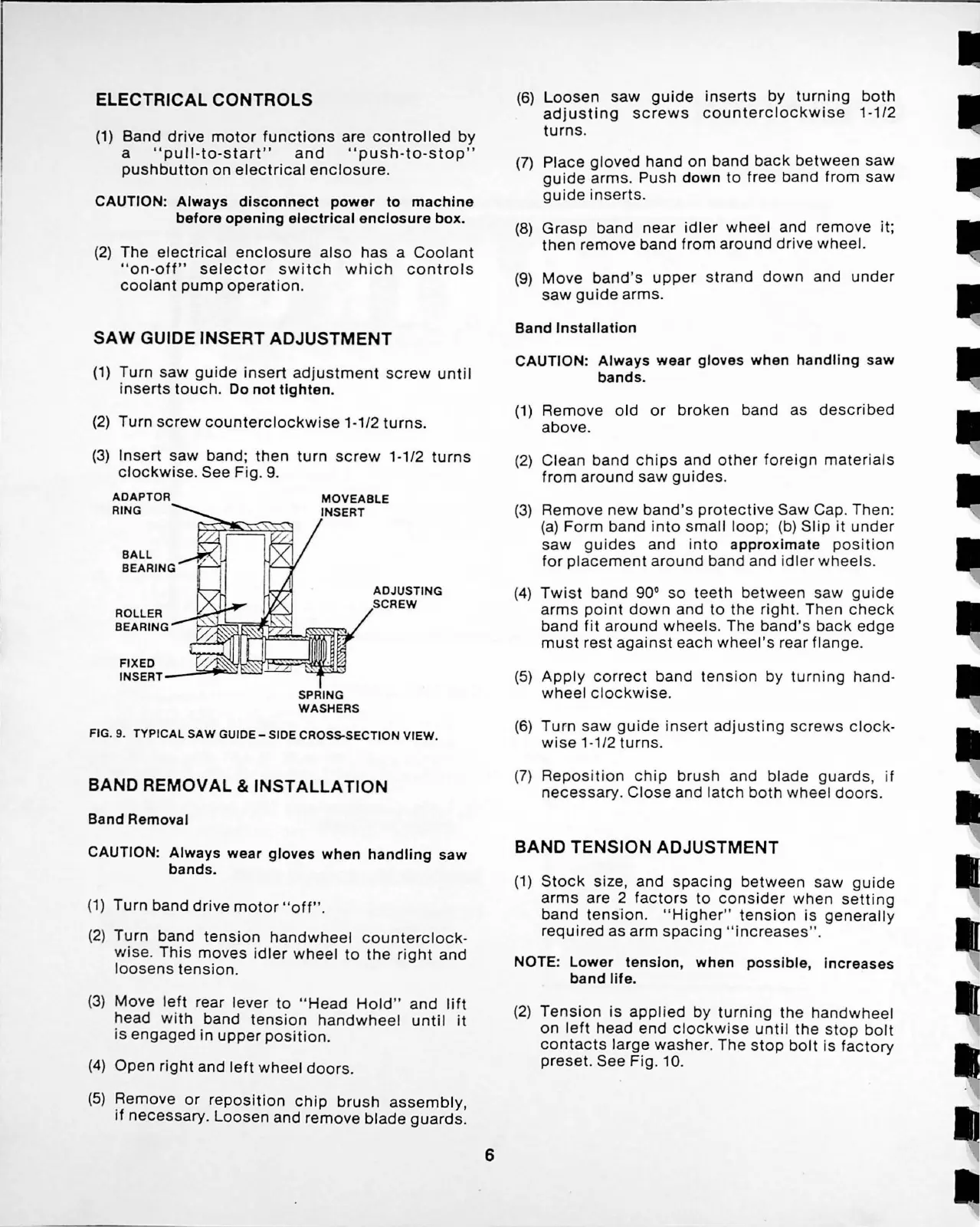
(3)
Insert
saw
band
;
then
turn
sc
rew
1-1/2
turns
clockwise.
See
Fig
. 9.
ADAPTOR
RING
/,
BALL
_..l?<
BEARING
ROLLER
BEARING
MOVEABLE
INSERT
SPRING
WASHERS
ADJUSTING
SCREW
FIG. 9.
TYPICAL
SAW
GUIDE-
SIDE CROSS-SECTION
VIEW
.
BAND REMOVAL & INSTALLATION
Band Removal
CAUTION: Always wear gloves when handling saw
bands.
(
1)
Turn
band
drive
motor
"
off
" .
(2)
Turn
band
tension
handwheel
counterclock
-
wis
e.
This
moves
idler
whe
el
to
th
e
right
and
loosens
tension
.
(3)
Mov
e
left
rear
lever
to
"Head
Hold
"
and
lift
head
with
band
tension
handwhe
el
until
it
is
engaged
in
upper
position.
(4)
Open
right
and
left
wheel
doors.
(5)
Remove
or
repos
i
tion
chip
brush
assembly
,
if
necessary.
Loosen
and
remove
blade
guards
.
6
(6)
Loosen
saw
guide
inserts
by
turning
both
adjusting
screws
counterclockwise
1-1/2
turns
.
(7)
Place
gloved
hand
on
band
back
between
saw
guide
arms.
Push down
to
free
band
from
saw
guide
inserts
.
(8)
Grasp
band
near
idler
wheel
and
remove
it
;
then
remove
band
from
around
drive
wheel.
(9)
Move
band's
upper
strand
down
and
under
saw
guide
arms.
Band Installation
CAUTION: Always wear gloves when handling saw
bands.
(1)
Remove
old
or
broken
band
as
described
above.
(2)
Clean
band
chips
and
other
f
oreign
materials
from
around
saw
gui
des
.
(3)
Remove
new
band's
protective
Saw
Cap
. Then:
(a)
Form
band
into
small
loop
; (b)
Slip
it
under
saw
guides
and
into
approximate
pos
i
tion
for
placement
around
band and i
dler
wheels.
(4)
Twist
band
90°
so
teeth
between
saw
guide
arms
point
down
and
to
the
right.
Then
check
band
fit
around
wheels
.
The
band's
back
edge
must
rest
against
each
wheel's
rear
flange.
(5)
Apply
correct
band
tension
by
turning
hand
-
wheel
clockwise
.
(6)
Turn
s
aw
gu
i
de
insert
adjusting
scr
e
ws
cloc
k-
wise
1-1/2
turns
.
(7)
Repos
i
tion
c
hip
brush
and
blade
guards
, if
necessary
.
Clo
se
and
la
tc
h
both
wh
eel
doors
.
BAND
TENSION
ADJUSTMENT
(1)
Stock
size
,
and
spacing
betwe
en
saw
guide
arms
are 2
factors
to
cons
ider
when
setting
band
tens
i on. "
Higher"
tension
is
gen
e
rally
required
as
arm
spacing
" i
ncreas
es" .
NOTE: Lower tension, when possible, increases
band life.
(2)
Tension
is
applied
by
turning
th
e
handwheel
on
left
head
end
clockwis
e
until
the s
top
bolt
contacts
large
washer
.
Th
e
stop
bolt
is fa
ctory
preset.
See
Fig.
10.
I
I