I
I
I
••
I
II
INSTALLATION
NOTE: All
"left",
"right",
"front",
and
"rear"
directions in this manual are as viewed when
facing left saw guide arm clamping knob.
LOCATION
(1)
Position
machine
to
allow
room
for
feeding
and
removing
stock
with
maximum
convenience
.
(2)
Allow
sufficient
space
for
head
elevation,
door
opening,
lubrication
and
maintenance
procedures.
(3)
Approximate
machine
floor
dimensions
are
78
inches
(1980
mm)
wide
by
57
inches
(1450
mm)
deep.
Approximate
head
down
height
is
53-1/8
inches
(1350 mm);
head
up
height
is
72-1/2
inches
(1840 mm).
Refer
to
Figs.
1-3
for
additional
dimensions
.
OSHA
NOTICE!
OSHA
Regulation
No.
1910.212
(8).
Machines
designed
for fixed location shall be securely
anchored to prevent walking or moving.
UNPACKING
(1)
Carefully
remove
all
crating,
coverings,
strapping,
etc.
(2)
Remove
wires
used
to
secure
doors
and
wheels
.
CAUTION: Do not remove drive motor blocking or
bracket holding head to base until the
unit has been lifted to its permanent
location.
(3)
Check
machine
for
broken
or
damaged
parts.
Refer
to
this
manual's
inside
front
cover
for
damage
claim
procedures
.
CLEANING
(1)
A
rust
preventive
coating
has
been
applied
to
all
exposed
bare
metal.
Use
solvent
to
remove
this
coating.
3
LIFTING
(1)
The
machine
and
stock
unloading
table
can
be
moved
into
position
with
a
fork
lift
truck
or
overhead
hoist.
(2)
Spread
lift
truck
forks
for
even
weight
distri-
bution
to
protect
against
stress
on
machine
frame.
Hoist
slings
should
be
padded
.
NOTE:
The
stock unloading table
and
conveyors
(if supplied) can
be
lifted by
either
method.
Relocation Procedures
Should
machine
relocation
become
necessary
at
a
later
date,
it
will
be
extremely
important
to
protect
against
undue
machine
frame
stress
.
Move
machine
by
fork
lift
truck
and
observe
the
following
precautions:
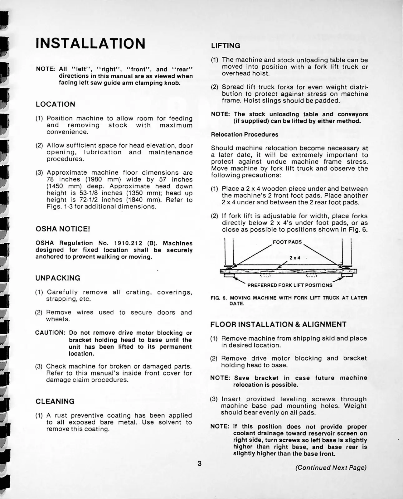
(1)
Place
a 2 x 4
wooden
piece
under
and
between
the
machine's
2
front
foot
pads
.
Place
another
2 x 4
under
and
between
the
2 rear
foot
pads.
(2)
If
fork
lift
is
adjustable
for
width,
place
forks
directly
below
2 x 4's
under
foot
pads,
or
as
close
as
possible
to
positions
shown
in
Fig.
6.
FOOTPADS
PREFERRED FORK
LIFT
POSITIONS
FIG. 6.
MOVING
MACHINE
WITH
FORK LIFT TRUCK
AT
LATER
DATE
.
FLOOR INSTALLATION &
ALIGNMENT
(1)
Remove
machine
from
shipping
skid
and
place
in
desired
location.
(2)
Remove
drive
motor
blocking
and
bracket
holding
head
to
base.
NOTE:
Save
bracket
in
case
future
machine
relocation is possible.
(3)
Insert
provided
leveling
screws
through
machine
base
pad
mounting
holes
.
Weight
should
bear
evenly
on
all
pads.
NOTE:
If
this position does not provide proper
coolant drainage toward reservoir screen on
right side, turn screws so left base is slightly
higher than right base,
and
base rear is
slightly higher than the base fronL
(Continued
Next
Page)