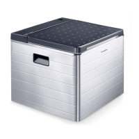
No. in fig.2, fig.3 Description
1 DC connection cable
2 AC connection cable
3 Control elements
4 Gas connection port (only ACX3 30 and ACX3 40)
4 Gas cartridge (only ACX3 40G)
5 Pilot light sight glass
5.2 Control elements
No. in fig.4, fig.5 Description
1 Cooling level controller (AC operation)
2 Cooling level controller (gas operation)
3 Ignition button
When the cooler is connected to the AC mains, the required cooling level is set using the cooling level controller
for AC operation (1).
To increase the cooling level, turn the cooling level controller ( 1) clockwise.
 Loading...