13
EN
VARC Chiller Controls General Information
5 Installation and Setup
The VARC can be installed as a stand-alone chiller or as
part of a staged system. The factory default setting is as a
stand-alone chiller.
Installation for a staged system requires the following
steps:
1. Make the connections between each stage of the
chilled water and sea water.
2. Make the network connections between each stage
(physical and network addressing).
3. Check the firmware version.
4. Configure the remote control panel.
Chillers supplied on a frame package are configured and
wired as part of the build process.
I
As part of a correctly configured multi-stage system
there is no need to set differential/hysteresis
settings.
5.1 Initial Wiring
WARNING: ELECTRICAL SHOCK HAZARD.
Exercise extreme care when working around
energized equipment. Failure to obey this warning
could result in death or serious injury.
1. Wire the sea water and chilled water pumps to
VARC 1 (no need for pump relays) as follows:
a. Remove the power cover.
b. Connect the pumps to the terminals on the front
of chiller 1, according to labeled connections.
Note: Daisy chaining outputs is not recommended if the
units have individual power sources. Verify the phase of
power before daisy chaining the outputs.
2. Wire the network connections from the network
connection ports (VARC 1 to VARC 2, VARC 2 to
VARC 3, and so forth).
Refer to the “Multi-stage Wiring” on page 14 for more
information on wiring the stages.
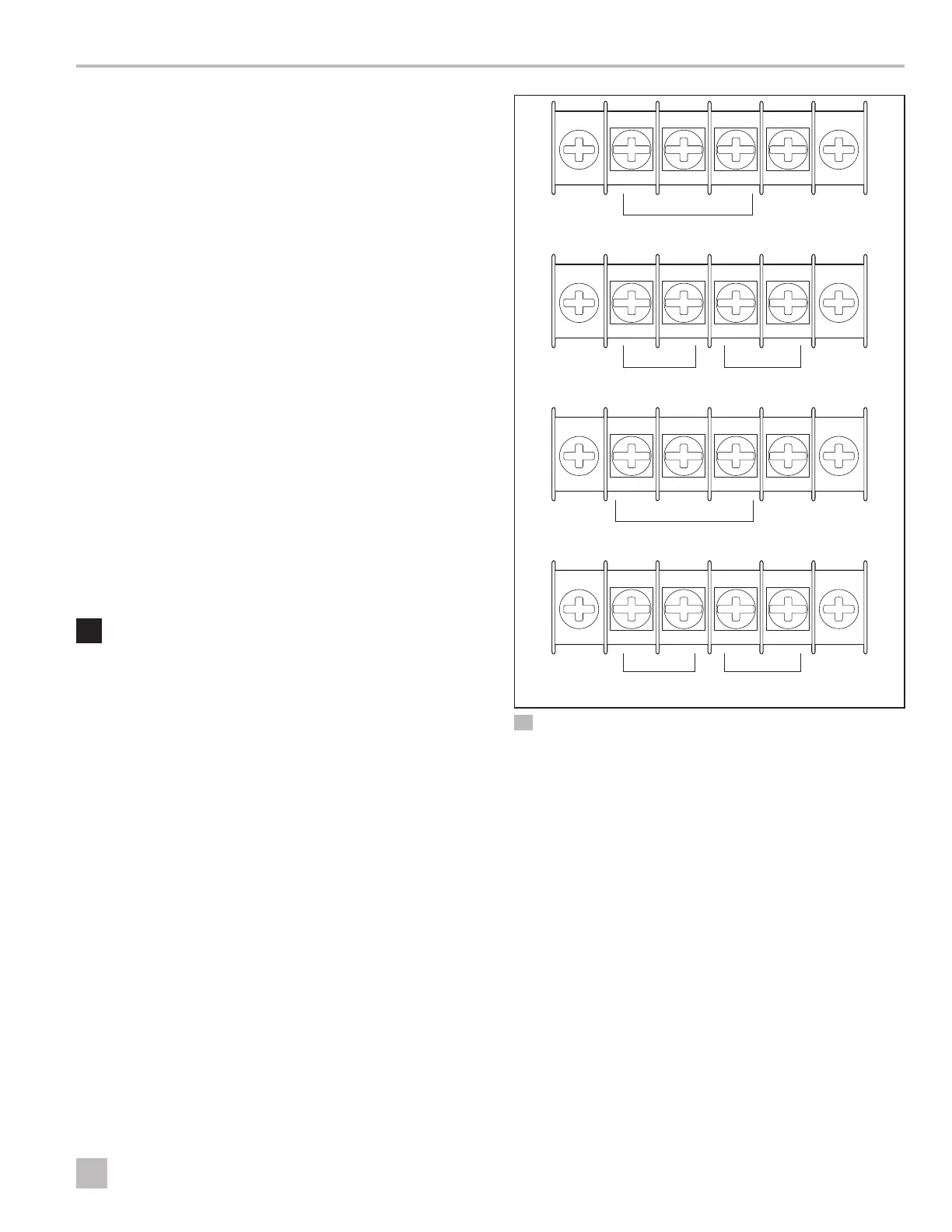
GND
GND
L2
L2
337430
337430
337430
337430
G L1 L2
GND R+/T+ R-/T-
L2
L2
L1
L1
L1
L1
w
q
e
r
t
y
4 Electrical Connections VARC 48
q
Power Input
r
Network Connection
and Touch Screen
w
SW Pump (10 A max.)
t
Load Shed Switch
e
CW Pump (10 A max.)
y
Elec. Heat Output